Internet-based indoor dustproof and anti-collision display screen
A technology of display screen and Internet, applied in the field of display screen, can solve the problem of not being able to be dustproof and anti-collision well, and achieve the effect of good dustproof and anti-collision effect, good installation effect and good dustproof effect.
- Summary
- Abstract
- Description
- Claims
- Application Information
AI Technical Summary
Problems solved by technology
Method used
Image
Examples
Embodiment 1
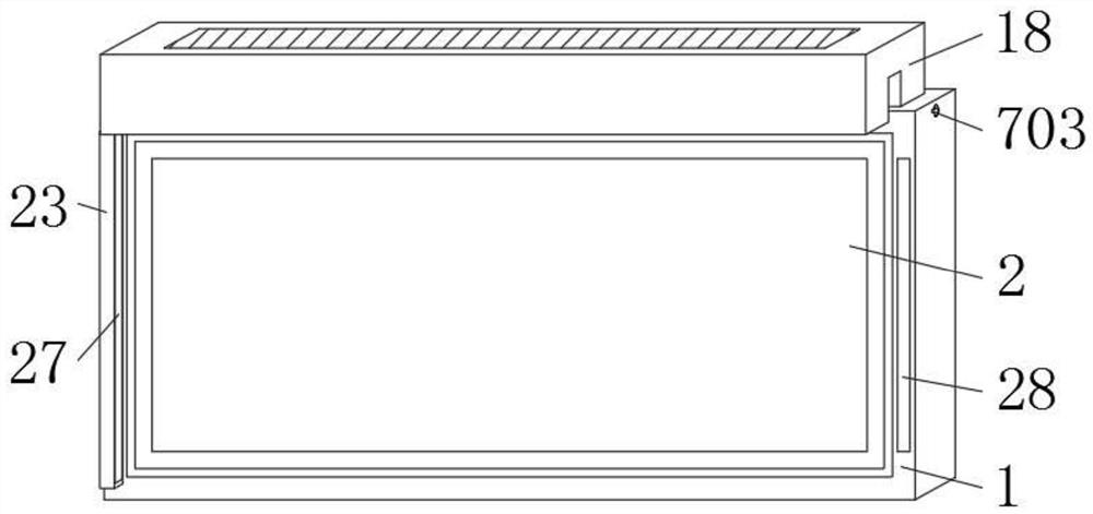
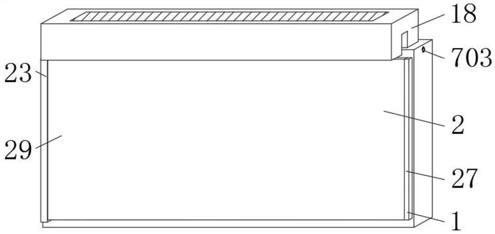
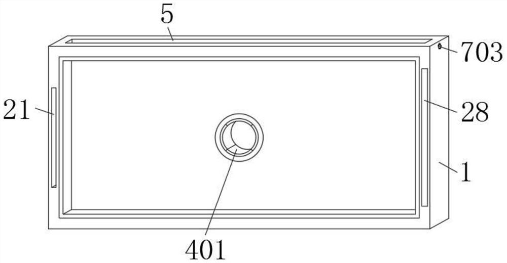
[0038] Such as Figure 1 to Figure 14 As shown, an Internet-based indoor dust-proof and bump-proof display screen provided by the embodiment of the present invention includes a fixed case 1 and a display screen 2, the display screen 2 is embedded in the fixed case 1, and the fixed case 1 has a Four cavities 3, the interior of the four cavities 3 are fixedly equipped with a shock absorbing mechanism 4, the top of the fixed shell 1 is provided with a square insertion groove 5, and the left and right sides of the fixed shell 1 are provided with placement grooves 6, two The inside of each placement slot 6 is fixedly equipped with a fixing mechanism 7, and the inside of the square plug-in slot 5 is plugged with a square plug-in block 8, and the left and right sides of the square plug-in block 8 are all provided with fixed slots 9, and the square plug-in block The front side of 8 is fixedly equipped with dust suction equipment 18, and the rear side of display screen 2 is fixedly ins...
Embodiment 2
[0046] refer to Figure 7 , the fixing mechanism 7 includes a circular block 701, the outer surface of the circular block 701 fits the inner wall of the placement groove 6, and the top and bottom of the left side of the circular block 701 are fixedly equipped with positioning posts 702, and the two positioning posts 702 are far away from One end of circular block 701 is all fixedly connected with the inwall of placement groove 6, and the internal thread of circular block 701 is connected with threaded rod 703, and the left side of threaded rod 703 is connected with T-shaped fixed block 704, and the T-shaped fixed block 704 The left side passes through the placement slot 6 and extends to the inside of the square insertion slot 5 , and the left side of the T-shaped fixing block 704 is plugged into the inside of the fixing slot 9 .
[0047] Adopt the above scheme: the power source of the whole fixing mechanism 7 is realized by manpower rotating the threaded rod 703, because the f...
Embodiment 3
[0054] refer to Figure 14 , the positioning mechanism 25 includes a pusher plate 2501, the outer surface of the pusher plate 2501 is slidingly connected with the inner wall of the storage cavity 24, the top and bottom of the front side of the pusher plate 2501 are fixedly equipped with moving blocks 2502, and the left sides of the two moving blocks 2502 Both are fixedly installed with circular columns 2503, and the ends of the two circular columns 2503 away from the moving block 2502 are used in conjunction with the inside of the mating block 22, and the left side of the push plate 2501 is fixedly equipped with a tension spring 2504, which is far away from the push plate 2501 One end is fixedly connected with the inner wall of the storage cavity 24, and the left side of the push plate 2501 is fixedly equipped with a push handle 2505, and the push handle 2505 is located inside the extension spring 2504.
[0055] The above scheme is adopted: the power source of the entire posit...
PUM
 Abstract
Description
Claims
Application Information
 - R&D
- Intellectual Property
- Life Sciences
- Materials
- Tech Scout
- Unparalleled Data Quality
- Higher Quality Content
- 60% Fewer Hallucinations
Browse by: Latest US Patents, China's latest patents, Technical Efficacy Thesaurus, Application Domain, Technology Topic, Popular Technical Reports.
© 2025 PatSnap. All rights reserved.Legal|Privacy policy|Modern Slavery Act Transparency Statement|Sitemap|About US| Contact US: help@patsnap.com


