
Conductive slip ring

A conductive slip ring and conductive ring technology, applied in the direction of circuits, current collectors, electrical components, etc., can solve the problems that cannot meet the needs of ultra-high speed equipment, achieve high rated speed and service life, and ensure reliability

Active Publication Date: 2021-08-13
SHENZHEN JINPAT ELECTRONICS
View PDF9 Cites 0 Cited by
  • Summary
  • Abstract
  • Description
  • Claims
  • Application Information

AI Technical Summary

Problems solved by technology

At present, the rotation speed of domestic conductive slip rings is about several thousand revolutions per minute, which cannot meet the requirements of ultra-high-speed equipment. Therefore, how to improve conductive slip rings to increase the rated speed has become a technical problem to be solved urgently by those skilled in the art.

Method used


Image

  • Conductive slip ring
  • Conductive slip ring
  • Conductive slip ring

Examples


Embodiment Construction

[0023] For ease of understanding, the present invention will be further described below in conjunction with the accompanying drawings.

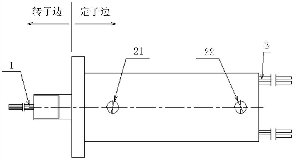
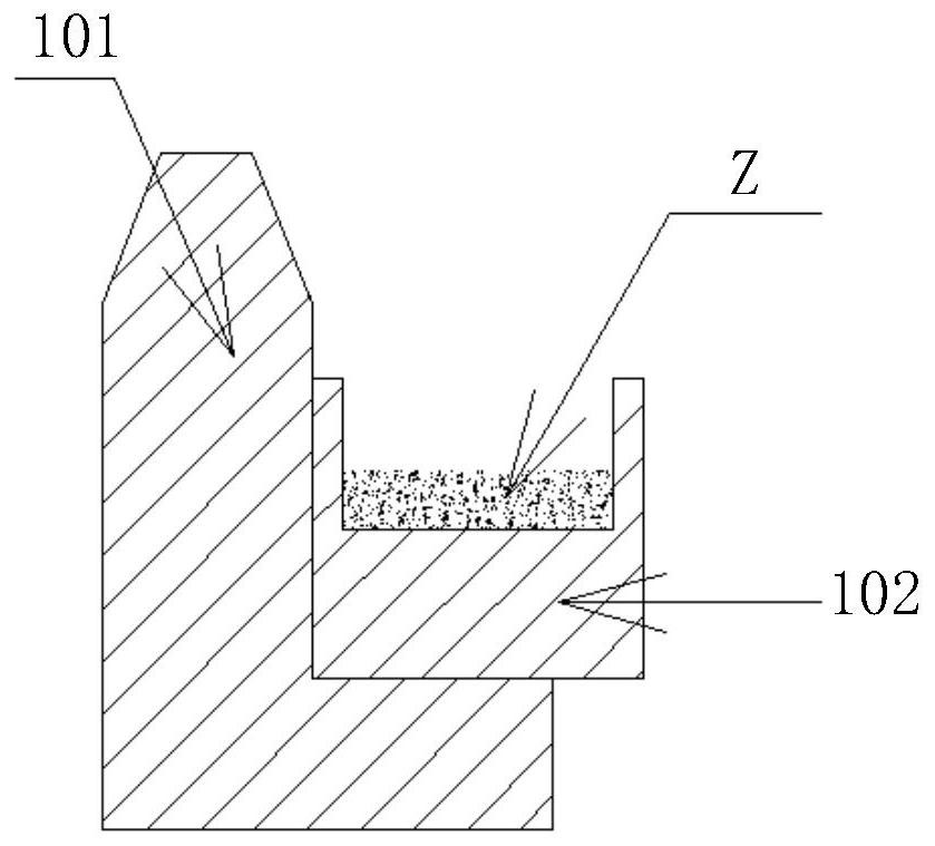
[0024] see figure 1 and figure 2 , figure 1 is a schematic diagram of the appearance of the conductive slip ring provided by the embodiment of the present invention, figure 2 It is a schematic diagram of the internal structure of the conductive slip ring provided by the embodiment of the present invention. The conductive slip ring provided by the embodiment of the present invention includes a stator and a rotor, wherein the stator includes a casing 2 and a bracket 8, the bracket 8 is located in the casing 2, and the rotor includes a main shaft 4 And the conductive ring 102, the main shaft 4 is installed in the bracket 8, the bracket 8 is provided with a brush holder board installation groove and bearing installation grooves on both sides of the brush holder board installation groove, the bracket 8 is located in the bearing installation gr...


PUM


Abstract

The invention provides a conductive slip ring which comprises a stator and a rotor; the rotor comprises a main shaft (4) and a conductive ring (102); the stator comprises a support (8) and a shell (2); the support is located in the shell; the main shaft is arranged in the support in a penetrating mode; the main shaft comprises a loop section used for installing a conducting ring, the surface of the loop section is provided with a plurality of wire passing grooves (44) which are evenly distributed in the circumferential direction, and the wire passing grooves (44) are filled with glue to form reinforcing bodies; an annular groove is formed in the outer surface of the conducting ring, and conducting grease is applied in the annular groove; the support is provided with a brush carrier plate installation groove and bearing installation grooves located in the two sides of the brush carrier plate installation groove, first air holes extending in the radial direction of the main shaft are formed in the portions, located between the bearing installation grooves and the brush carrier plate installation groove, of the support, and second air holes are formed in the portions, corresponding to the first air holes, of the shell; and the second air holes are connected with cooling air pipelines located outside the shell. The conductive slip ring provided by the invention has a relatively high rated speed and a relatively long service life.

Description

technical field [0001] The invention relates to the technical field of slip rings, in particular to a conductive slip ring. Background technique [0002] In recent years, the market has higher and higher requirements for the speed of slip rings, especially in ultra-high speed equipment in aerospace, medical, scientific research and military industries, etc., the transfer of electrical signals requires both functionality and stability. At present, the rotation speed of domestic conductive slip rings is about several thousand revolutions per minute, which cannot meet the requirements of ultra-high speed equipment. Therefore, how to improve conductive slip rings to increase the rated speed has become a technical problem to be solved urgently by those skilled in the art. Contents of the invention [0003] In view of this, the present invention provides a conductive slip ring, which has a relatively high rated speed and service life. [0004] In order to achieve the above obje...

Claims


Application Information

Patent Timeline
Patent Type & Authority Applications(China)
IPC IPC(8): H01R39/08H05K7/20
CPCH01R39/08H05K7/20136H05K7/202
Inventor 蔡益军
Owner SHENZHEN JINPAT ELECTRONICS
Learn More