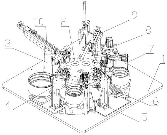
A female connector automatic assembly machine
An automatic assembly machine and connector technology, applied in the assembly/disassembly of contacts, can solve the problems of unstable production quality, low degree of automation and high labor intensity, and achieve the effect of simple structure, labor saving and labor intensity reduction.
- Summary
- Abstract
- Description
- Claims
- Application Information
AI Technical Summary
Problems solved by technology
Method used
Image

Examples
Embodiment 2
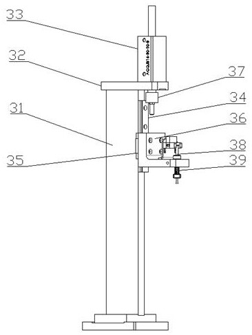
[0031] Embodiment 2: as figure 2 As shown, the detection mechanism 3 includes a detection support frame 31, the top of the detection support frame 31 is provided with a detection installation plate 32 horizontally, and a detection cylinder 33 is vertically arranged on the detection installation plate 32. The working end of the detection cylinder 33 A detection cylinder connecting block 37 is connected through the detection support frame 31 , a detection slide rail 34 is vertically arranged on the upper side of the detection support frame 31 , and a detection slide rail sleeve 35 is slidably connected to the detection slide rail 34 . A detection portion mounting plate 36 is fixedly arranged, a first photoelectric switch mounting seat is vertically arranged in the middle of the detection portion mounting plate 36, and a first photoelectric switch is arranged on the front end of the first photoelectric switch mounting seat. The first photoelectric switch A first detection rod 38...
Embodiment 3
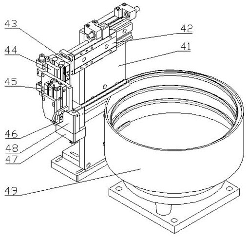
[0032] Embodiment 3: as image 3 As shown, the casing feeding mechanism 4 includes a casing feeding support frame 41, and a casing feeding cylinder 42 is horizontally arranged on the upper part of the casing feeding supporting frame 41, and the casing feeding cylinder 42 works The first cylinder fixing plate 43 is vertically arranged at the end, the front end surface of the first cylinder fixing plate 43 is vertically arranged with a first cylinder 44, and the working end of the first cylinder 44 is vertically arranged with a first finger cylinder fixing plate. A first finger cylinder 45 is vertically arranged at the front end of the fixing plate of a finger cylinder, the working ends of the first finger cylinder 45 are respectively provided with housing clips 46 opposite to each other, and the front end of the first finger cylinder 45 is vertically arranged with a first finger cylinder to lift The middle part of the casing feeding support frame 41 is horizontally provided wit...
Embodiment 4
[0033] Embodiment 4: as Figure 4 As shown, the bearing feeding mechanism 5 includes a bearing feeding support frame 51, the upper part of the bearing feeding support frame 51 is provided with a second cylinder 52 horizontally, and the working end of the second cylinder 52 is vertically provided with a third cylinder 53 The working end of the third cylinder 53 is vertically provided with a second finger cylinder mounting plate 54, the front end of the second finger cylinder mounting plate 54 is horizontally provided with a first fixing block 55, and the middle of the first fixing block 55 is vertically arranged There is a second photoelectric switch mounting plate, a second photoelectric switch is arranged in the middle of the second photoelectric switch installation plate, a second detection rod 56 is vertically arranged through the middle of the front end of the second photoelectric switch, and the upper end of the second detection rod 56 The surface is provided with a third...
PUM
 Abstract
Description
Claims
Application Information
 - R&D
- Intellectual Property
- Life Sciences
- Materials
- Tech Scout
- Unparalleled Data Quality
- Higher Quality Content
- 60% Fewer Hallucinations
Browse by: Latest US Patents, China's latest patents, Technical Efficacy Thesaurus, Application Domain, Technology Topic, Popular Technical Reports.
© 2025 PatSnap. All rights reserved.Legal|Privacy policy|Modern Slavery Act Transparency Statement|Sitemap|About US| Contact US: help@patsnap.com