
Box girder pouring equipment

A kind of equipment and box girder technology, applied in the field of box girder pouring equipment, can solve problems such as damage and waste, achieve the effect of reducing cost and waste, and speeding up the pouring rate

Active Publication Date: 2021-08-17
上海远东杨园道桥有限公司
View PDF10 Cites 0 Cited by
  • Summary
  • Abstract
  • Description
  • Claims
  • Application Information

AI Technical Summary

Problems solved by technology

[0004] The above-mentioned related technical solutions have the following defects: the above-mentioned box girder needs to be built with an inner mold and an outer mold for pouring and molding during production, and then steel bars are placed between the inner mold and the outer mold and concrete is poured until the concrete is completely solidified and formed. Then destroy the inner mold and outer mold to form a concrete box girder, so that each box girder needs to destroy a copy of the inner mold and outer mold, which is very wasteful

Method used


Image

  • Box girder pouring equipment
  • Box girder pouring equipment
  • Box girder pouring equipment

Examples


Embodiment Construction

[0040] The following is attached Figure 1-8 The application is described in further detail.

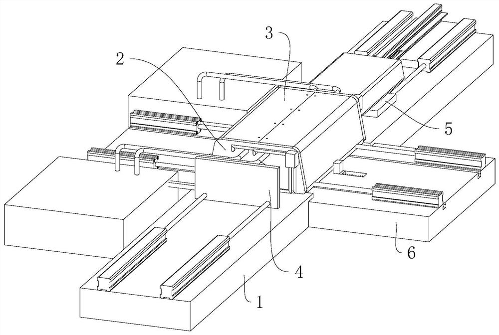
[0041] see figure 1 , a box girder pouring equipment, including machine base 1, pouring inner mold 2, pouring outer mold 3, and a mobile seat 4 and a forming slide 5 that are horizontally slidably arranged on the upper end of the machine base 1.

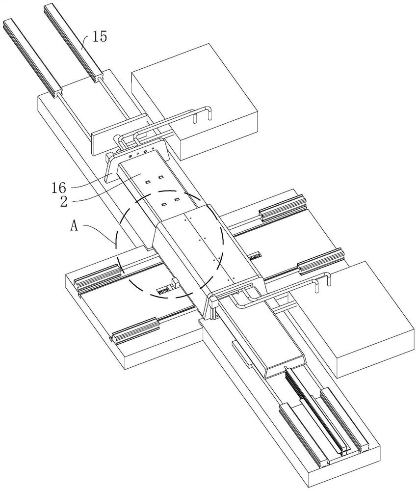
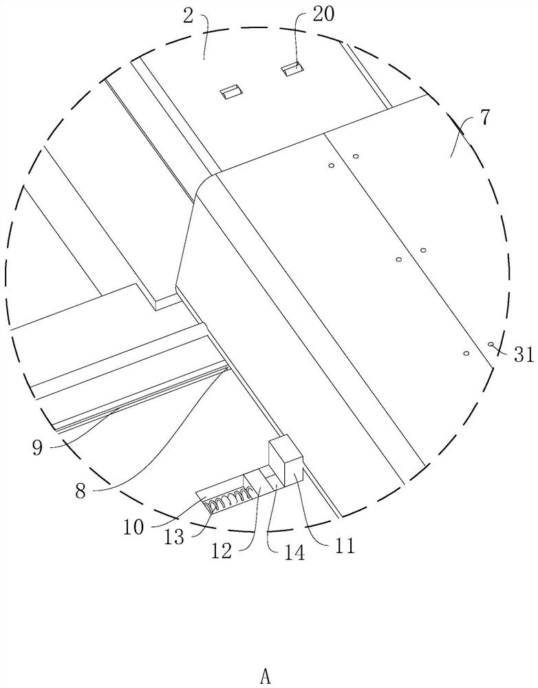
[0042] see figure 2 with image 3 The two sides of the middle part of the machine base 1 are integrally provided with supporting slides 6, the supporting slides 6 are perpendicular to the machine base 1, the two supporting slides 6 and the machine base 1 form a "ten" shape, and the pouring outer mold 3 includes two halves The mold casing 7, the structure and shape of the two half mold casings 7 are exactly the same, and at the same time, the central axis of the machine base 1 is symmetrical, the upper ends of the two half mold casings 7 are in contact, and the lower ends of the two half mold casings 7 are respectively provided with two ...


PUM


Abstract

The invention relates to box girder pouring equipment. The equipment comprises a machine base and a movable base horizontally arranged at the upper end of the machine base in a sliding mode, a pouring outer mold is arranged at the upper end of the machine base, a pouring inner mold inserted into the middle of the pouring outer mold in a sliding mode is arranged at the side end, close to the pouring outer mold, of the movable base, a pouring support is embedded between the pouring outer mold and the pouring inner mold, and the pouring support comprises an outer supporting sleeve attached to the inner circumferential wall of the pouring outer mold, an inner supporting sleeve attached to the outer circumferential wall of the pouring inner mold and steel bars supported between the inner supporting sleeve and the outer supporting sleeve. The equipment has the characteristics that: the pouring outer mold and the pouring inner mold can be continuously used, the pouring efficiency and quality are high, and pouring is convenient.

Description

technical field [0001] The present application relates to the technical field of concrete bridges, in particular to a box girder pouring equipment. Background technique [0002] At present, steel-concrete composite structure is the fifth largest type of structure developed after wood structure, masonry structure, reinforced concrete structure and steel structure. Steel-concrete composite beam is a kind of steel-concrete composite structure, which refers to the steel-concrete composite beam composed of I-beam or H-shaped steel and concrete filled in the flanges on both sides. The material properties of concrete can effectively improve the bearing capacity, ductility and seismic performance of composite beams. Specifically, the concrete in the flanges on both sides of composite beams is in a three-dimensional stress state due to the wrapping of flanges and webs, which has a certain restraint effect. , the profile steel of the composite beam can effectively restrain the occurr...

Claims


Application Information

Patent Timeline
Patent Type & Authority Applications(China)
IPC IPC(8): E01D21/00E01D2/04E01D101/26
CPCE01D21/00E01D2/04E01D2101/26
Inventor 戚燕莉
Owner 上海远东杨园道桥有限公司
Learn More