
Warm air system

A heating system and fan technology, applied in the field of heating systems, can solve problems such as adverse effects on health, air pollution, and environmental pollution

Pending Publication Date: 2021-08-17
青岛暖梦达节能科技有限公司
View PDF0 Cites 0 Cited by
  • Summary
  • Abstract
  • Description
  • Claims
  • Application Information

AI Technical Summary

Problems solved by technology

[0002] In the northern region of my country, central heating has become the mainstream heating method in winter, while the southern region mainly relies on air conditioning for heating. Compared with the two, central heating is stable and comfortable, but its source heat company mainly relies on coal-fired, so it often happens Seeing that the chimneys of the heating company emit a large amount of exhaust gas, which is easy to cause environmental pollution. In order to meet the exhaust emission standards, environmental protection equipment must be added, which will increase costs and increase the cost of central heating; while air conditioning is low in heating efficiency and belongs to indoor air. Single circulation can easily cause air pollution, lead to air-conditioning diseases, and have adverse effects on people's health
However, in most rural areas of our country, households are used as the unit, and old-fashioned coal-fired stoves are used for heating in winter. Carbon monoxide poisoning incidents often occur in this heating method, which poses a threat to people's lives and is one of the important causes of air pollution. , are on the verge of being eliminated

Method used


Image

  • Warm air system
  • Warm air system

Examples


Embodiment Construction

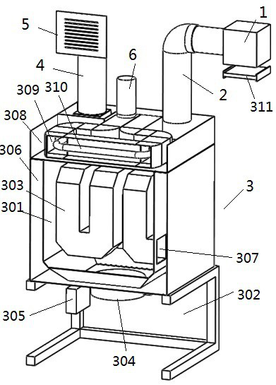
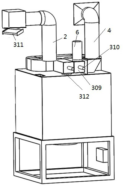
[0021] The present invention will be described in further detail below in conjunction with the accompanying drawings. In order to clearly show the internal structure of the gas heating stove, the gas heating stove in the figure does not draw the shell and other structures on the shell.

[0022] refer to figure 1 and figure 2 , a new type of warm air system, the technical solution it adopts is: a kind of warm air system, which is characterized in that it includes an outdoor fan 1, a gas heating furnace 3 connected to the outdoor fan through an air inlet pipe 2, and a gas heating The heating furnace is connected to the indoor perfusion fan 5 through the air outlet pipe 4, wherein the gas heating furnace includes: a casing (not shown in the figure), an air heating chamber 301 and a functional chamber 302 located in the casing, and the air heating chamber is located in the functional The air heating room is above the room and communicated with the functional room; the air heati...


PUM


Abstract

The invention discloses a warm air system, which comprises an outdoor fan, a gas heating stove connected with the outdoor fan through an air inlet pipeline and an indoor perfusion fan connected with the gas heating stove through an air outlet pipeline, wherein the gas heating stove comprises a shell, an air heating chamber and a function chamber located in the shell, and the air heating chamber is positioned above the function chamber and is communicated with the function chamber; an air heating pipeline is arranged in the air heating chamber; a gas heating furnace head and a corresponding electric control device are arranged in the function chamber; a preheating air duct is arranged in the circumferential direction of the air heating chamber, and a first air inlet communicated with the air inlet pipe is arranged above the preheating air duct; a second air inlet communicated with the front end of the air heating pipeline is arranged below the preheating air duct; the rear end of the air heating pipeline is communicated with the air outlet pipeline; a smoke outlet is arranged above the heating chamber and connected to the outside through a smoke outlet pipe; and an air inlet for supplying oxygen to the air heating chamber is arranged on the shell corresponding to the function chamber.

Description

technical field [0001] The invention relates to an air conditioning system, in particular to a heating system. Background technique [0002] In the northern part of my country, central heating has become the mainstream heating method in winter, while the southern part mainly relies on air conditioning for heating. Compared with the two, central heating is stable and comfortable, but its source heat company mainly relies on coal-fired, so it often happens Seeing that the chimneys of the thermal company emit a large amount of exhaust gas, which is easy to cause environmental pollution. In order to meet the exhaust emission standards, environmental protection equipment must be added, which will increase costs and increase the cost of central heating; while air conditioning is low in heating efficiency and belongs to indoor air. Single circulation can easily cause air pollution, lead to air-conditioning diseases, and have adverse effects on people's health. However, in most rural...

Claims


Application Information

Patent Timeline
IPC IPC(8): F24H3/08F24H9/18F24H9/12
CPCF24H3/081F24H9/12F24H9/1863
Inventor 谢晓琨
Owner 青岛暖梦达节能科技有限公司
Learn More