
Mixed-flow type spray propulsion cooling device

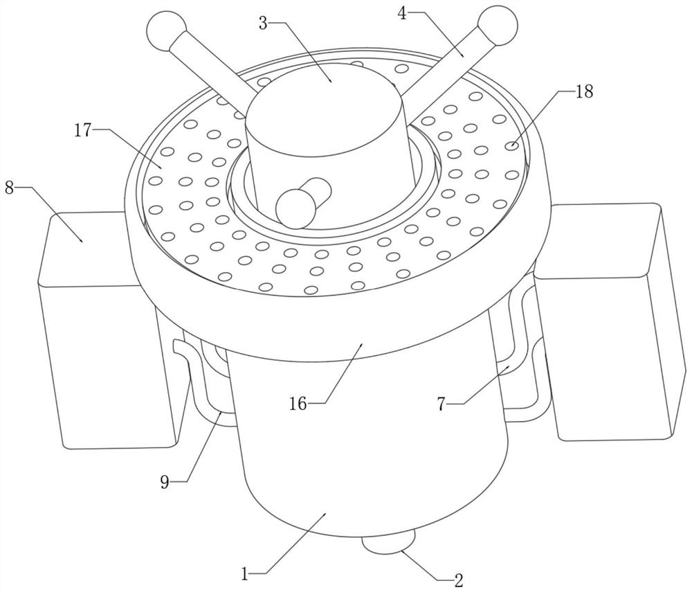
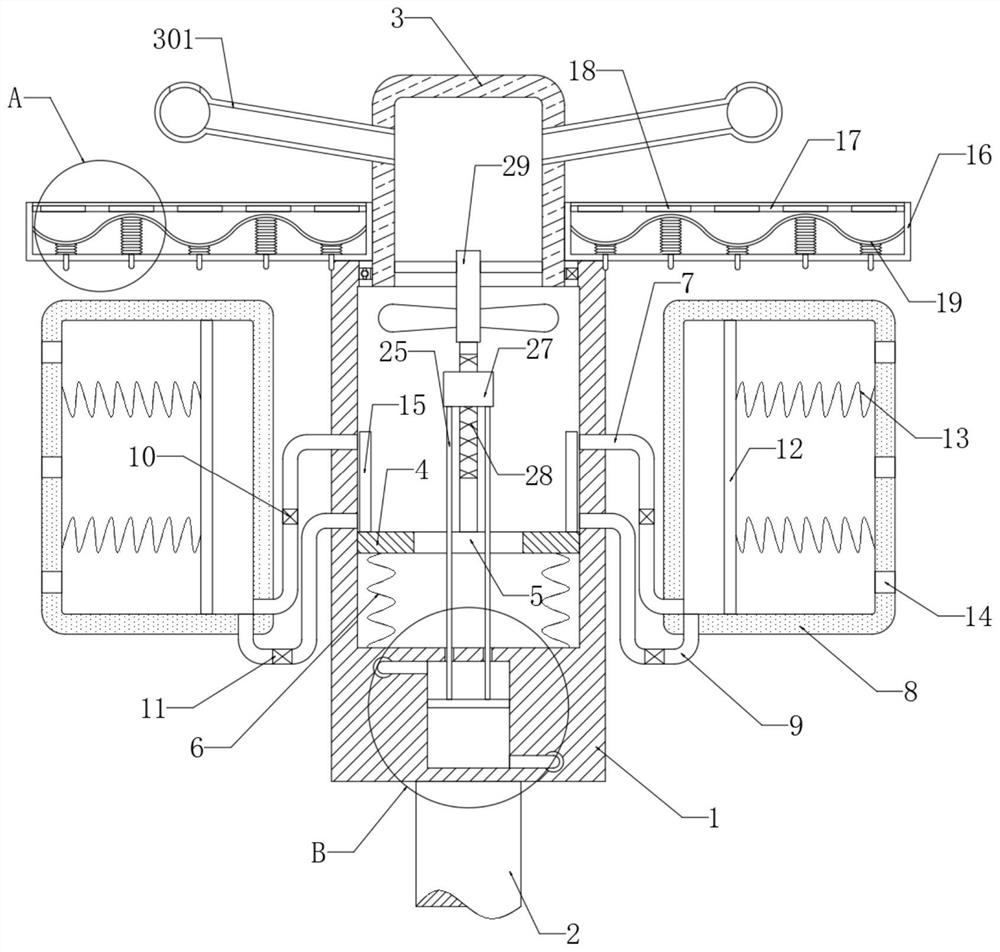
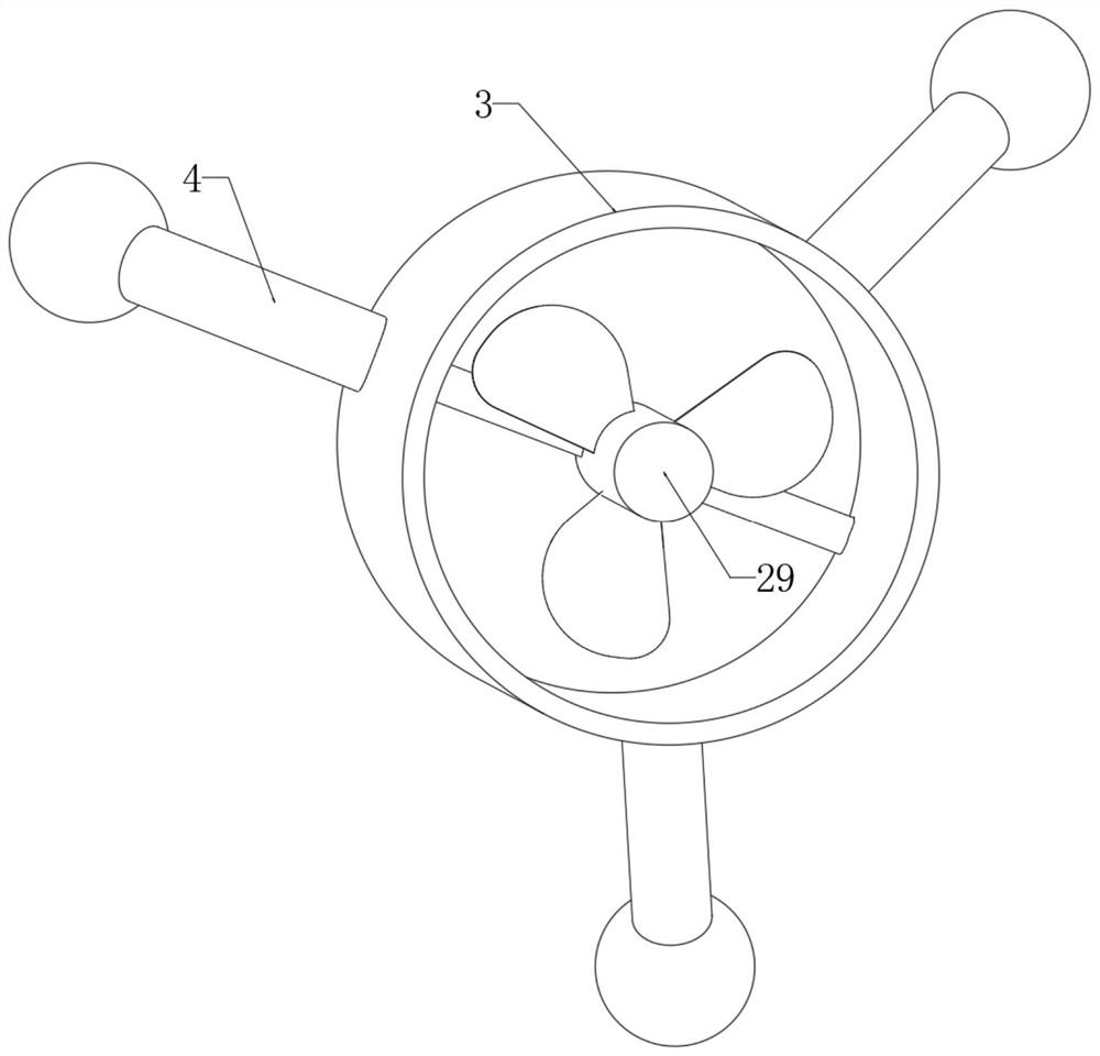
A cooling device, mixed-flow technology, applied in water shower coolers, direct contact heat exchangers, heat exchanger types, etc., can solve the problems of small spray area, fluctuating water flow pressure, and large changes in inlet water flow. , to achieve the effect of improving the cooling efficiency and prolonging the contact time

Active Publication Date: 2021-08-17
山东旭能环保科技有限公司
View PDF6 Cites 1 Cited by
  • Summary
  • Abstract
  • Description
  • Claims
  • Application Information

AI Technical Summary

Problems solved by technology

[0003] This driving method is very dependent on the kinetic energy of the sprayed water flow, that is, the water flow pressure. In the actual use process, the water flow rate changes greatly and the water flow pressure fluctuates. When the water flow pressure is high, the spray propulsion device rotates fast and the water body The atomization effect is good and the water mist spraying area is wide, but when the water pressure is low, the water mist effect is poor and the spraying area is small, so that the cooling effect of the cooling tower also changes continuously, and the cooling effect is unstable, especially when the water pressure is small, the cooling The effect is very unsatisfactory

Method used


Image

  • Mixed-flow type spray propulsion cooling device
  • Mixed-flow type spray propulsion cooling device
  • Mixed-flow type spray propulsion cooling device

Examples


Embodiment Construction

[0023] The following will clearly and completely describe the technical solutions in the embodiments of the present invention with reference to the accompanying drawings in the embodiments of the present invention. Obviously, the described embodiments are only some, not all, embodiments of the present invention.

[0024] In describing the present invention, it should be understood that the terms "upper", "lower", "front", "rear", "left", "right", "top", "bottom", "inner", " The orientation or positional relationship indicated by "outside", etc. is based on the orientation or positional relationship shown in the drawings, and is only for the convenience of describing the present invention and simplifying the description, rather than indicating or implying that the referred device or element must have a specific orientation, so as to Specific orientation configurations and operations, therefore, are not to be construed as limitations on the invention.

[0025] refer to Figure ...


PUM


Abstract

The invention discloses a mixed-flow type spray propulsion cooling device which comprises a variable-speed cylinder. A water inlet pipe communicating with the variable-speed cylinder is arranged at the lower end of the variable-speed cylinder; a rotating cylinder is rotatably connected to the inner wall of the variable-speed cylinder through a sealing bearing; multiple spray pipes communicating with the interior of the rotating cylinder are installed on the side wall of the rotating cylinder; a liquid inlet pipe and a liquid outlet pipe communicating with the interior of the variable-speed cylinder are installed on the variable-speed cylinder; the ends, away from the variable-speed cylinder, of the liquid inlet pipe and the liquid outlet pipe jointly communicate with a liquid storage tank; a liquid discharging device for discharging liquid to the variable-speed cylinder is installed in the liquid storage tank; and a baffle is connected into the variable-speed cylinder in a sealed and sliding mode. According to the mixed-flow type spray propulsion cooling device provided by the invention, by arranging the liquid storage tank, the liquid discharging device, the liquid inlet pipe, the liquid outlet pipe and other components, part of water can be guided into the liquid storage tank so as to be stored when the water flow pressure is large, and when the water flow pressure is small, a push plate is pushed through a second spring so as to extrude out water in the liquid storage tank, so that the water flow pressure can be kept stable and balanced, and the cooling tower obtains a stable and effective cooling effect.

Description

technical field [0001] The invention relates to the technical field of cooling tower related equipment, in particular to a mixed-flow spray propulsion cooling device. Background technique [0002] The mixed-flow spray cooling tower is a common cooling equipment in the chemical industry. It can spray cooling water into mist to quickly evaporate and absorb heat. Wherein the spray propulsion device is a very important part, which mainly drives the spray head and the spray propeller connected to it to rotate around the central axis through the kinetic energy of the sprayed water. [0003] This driving method is very dependent on the kinetic energy of the sprayed water flow, that is, the water flow pressure. In the actual use process, the water flow rate changes greatly and the water flow pressure fluctuates. When the water flow pressure is high, the speed of the spray propulsion device is fast and the water body The atomization effect is good and the water mist spraying area is...

Claims


Application Information

Patent Timeline
IPC IPC(8): F28C1/06F28F25/04F28F25/02F28F25/06
CPCF28C1/06F28F25/04F28F25/02F28F25/06
Inventor 刘小刚潘锡武王丹
Owner 山东旭能环保科技有限公司
Features
  • Generate Ideas
  • Intellectual Property
  • Life Sciences
  • Materials
  • Tech Scout
  • Unparalleled Data Quality
  • Higher Quality Content
  • 60% Fewer Hallucinations
Learn More