
Transparent one-way light-emitting light source module

A technology of one-way light output and light source module, which is applied in the light guide, light guide, optics and other directions of the lighting system, which can solve the problems of high cost, complicated process, and reduced light transmittance, and achieve good collimation, high transparency, Effects with low production difficulty and low cost

Active Publication Date: 2021-08-17
MAANSHAN JINGZHI TECH CO LTD
View PDF16 Cites 1 Cited by
  • Summary
  • Abstract
  • Description
  • Claims
  • Application Information

AI Technical Summary

Problems solved by technology

There is light leakage on the back side. Although the back side is attached with a semi-transparent and semi-reflective film, which can suppress the light leakage on the back side, it will reduce the light transmittance. At the same time, the semi-transparent and semi-reflective structure must be aligned with the microstructure on the opposite side, so the process is complicated ,higher cost

Method used


Image

  • Transparent one-way light-emitting light source module
  • Transparent one-way light-emitting light source module
  • Transparent one-way light-emitting light source module

Examples


Embodiment 1

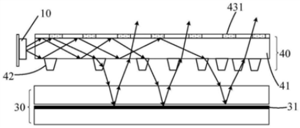
[0027] Embodiment one: if Figure 4 As shown, a transparent one-way light emitting light source module includes a light source 1 and a wedge-shaped light guide plate 2. The wedge angle is γ. The wedge-shaped light guide plate 2 includes a light incident surface 20, a first surface 21 and a second surface 22. The first surface 21 is provided with a bonding layer 3, and the material of the wedge-shaped light guide plate 2 is PC, PMMA or glass with a refractive index of 1.5 to 1.7, which is greater than the refractive index of the bonding layer 3 or more than 0.05. The material of the bonding layer 3 can choose a refractive index 1.5-1.3 PMMA, silica gel, acrylic resin or epoxy resin, etc., the light emitted by the light source 1 enters the wedge-shaped light guide plate 2, and when the light 201 reaches the first surface 21 at the junction of the wedge-shaped light guide plate 2 and the bonding layer 3, it is incident The angle is α, when α is greater than the total reflection a...

Embodiment 2

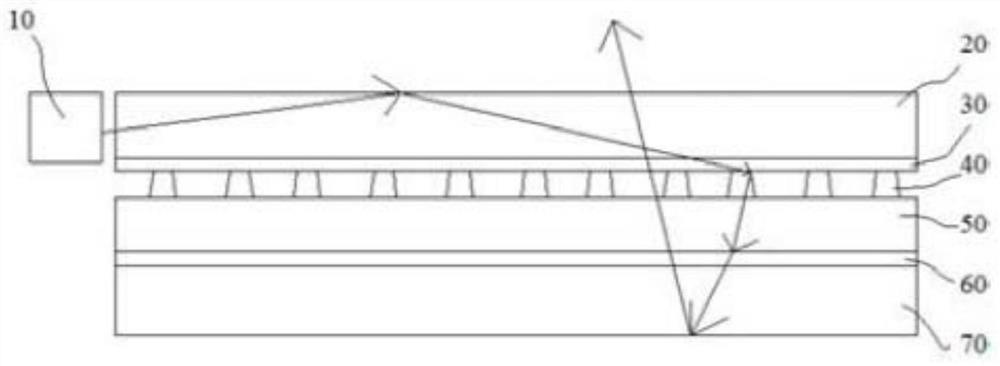
[0029] Embodiment two: if Image 6 As shown, on the basis of Embodiment 1, a protective layer 5 is provided on the side of the second surface 22 of the wedge-shaped light guide plate 2 facing away from the bonding layer 3, and the refractive index of the protective layer 5 is lower than that of the bonding layer, so For the light in the wedge-shaped light guide plate 2, the total reflection angle α of the bonding layer 3 on the first surface 21 is greater than the total reflection angle Ω of the protective layer 5 on the second surface 22, so the light 202 is on the second surface Total reflection will occur when it is on the surface 22, but total reflection may not occur when it is on the first surface 21. Since after each total reflection, the speed of light 202 approaching the total reflection angle is 2γ degrees, so the total reflection angle α only needs to be greater than the total reflection angle Ω by 2γ degrees, that is

[0030] α-Ω≥2γ

[0031] So the refractive ind...

Embodiment 3

[0034] Embodiment three: as Figure 7 As shown, on the basis of Embodiment 1, a trumpet-shaped first auxiliary light guide plate 6 is integrally provided on the side of the wedge-shaped light guide plate 2 facing the light source 1, and the included angle of the horn mouth is θ, which includes two auxiliary surfaces 23 and 24. When the light irradiates on the auxiliary surfaces 23 and 24, the light will be effectively collimated. When the light 301 is irradiated on the auxiliary surface 23, total reflection occurs on the surface 23, and its travel angle is deflected by θ degrees in the counterclockwise direction. The light 302 When it is irradiated on the auxiliary surface 24, total reflection occurs on the surface 24, and its travel angle is deflected by θ degrees in the clockwise direction, so the light rays 301 and 302 are collimated after passing through the auxiliary surfaces 23 and 24, and then the light rays reach the first surface 21 , the incident angle α of the rays ...


PUM

PropertyMeasurementUnit
refractive indexaaaaaaaaaa

Abstract

The invention discloses a transparent one-way light-emitting light source module comprises a light source and a light guide plate; the light guide plate comprises a light-in surface, a first surface and a second surface; the transparent one-way light-emitting light source module is characterized in that an attaching layer is arranged on the first surface, and the refractive index of the light guide plate is larger than that of the attaching layer; and the module has the advantages that each component is simple in structure and low in manufacturing difficulty and cost, single-side light emitting can be effectively realized, generated parallel light beams with expanded sections are good in collimation, the whole module is extremely high in transparency, and the module has great compatibility with other technologies.

Description

technical field [0001] The invention relates to a light source module, in particular to a transparent one-way light emitting light source module. Background technique [0002] With the development of display technology and the needs of different display scenarios, new display systems have great market prospects, such as reflective liquid crystal display systems that are more energy-efficient and eye-friendly, electronic paper display systems, and transparent display systems with more cutting-edge applications. , but the light sources required by these systems are required to have high transparency and good unidirectional light output, so the transparent unidirectional light output light source system is the prerequisite for these new display systems to be applied to the market. The present invention proposes a high Transparent one-way light source module. [0003] Patent US20180052274A1 is a thin film light guide film, such as figure 1 As shown, a microstructure is made on...

Claims


Application Information

Patent Timeline
Patent Type & Authority Applications(China)
IPC IPC(8): G02B6/00
CPCG02B6/005G02B6/0036
Inventor 武鹏周淑金吕林忠李同
Owner MAANSHAN JINGZHI TECH CO LTD
Learn More