Scan driving unit, scan driving circuit, array substrate and display
A technology of scanning driving circuit and driving unit, which is applied in the field of scanning driving unit, scanning driving circuit, array substrate and display, and can solve the problems that the display cannot display normally, the EOA driving unit cannot output driving signals, etc.
- Summary
- Abstract
- Description
- Claims
- Application Information
AI Technical Summary
Problems solved by technology
Method used
Image
Examples
Embodiment 1
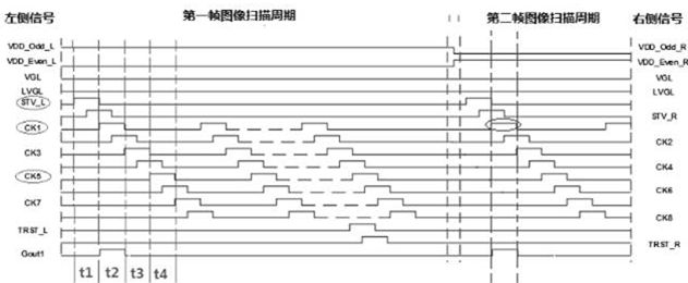
[0094] It should be noted that the "odd variable level power supply" and "even variable level power supply" mentioned in this embodiment are all DC power supplies with variable level, for example, "odd variable level power supply "It can be a high-level power supply in the first frame image scanning period and output a high-level signal; it can be a low-level power supply in the second frame image scanning period and output a low-level signal.
[0095] "Odd variable-level power supply" has the same function as "even variable-level power supply", and it can also be a high-level power supply during the first frame image scanning cycle and output a high-level signal; during the second frame image scanning cycle It is a low-level power supply and outputs a low-level signal. However, the "odd variable level power supply" can also be a low-level power supply in the first frame image scanning period, and output a low-level signal; it can be a high-level power supply in the second fra...
Embodiment 2
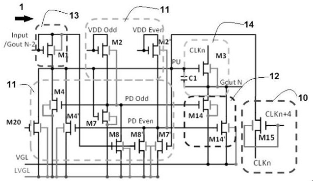
[0183] Figure 4 is a schematic circuit diagram of a scanning drive unit shown according to an exemplary embodiment, as shown in Figure 4 As shown, the scan driver unit includes:
[0184] The EOA drive unit 2 is electrically connected to the pull-up node EPU and the pull-down node EPD with a pull-down control unit 21, and the pull-down control unit 21 is used to control the pull-up node EPU to remain constant during the AGO phase when the gate line is fully open. In the low level state, the pull-down node EPD remains in a normally high level state, so that the EOA driving unit outputs a normally low level signal.
[0185] It can be understood that, in the technical solution provided by this embodiment, for the EOA drive unit, since the pull-down control unit 11 controls the pull-down node EPD to maintain a constant high level state during the AGO phase when the gate line is fully open, the pull-up node EPU maintains a constant high level state. The low-level state makes the...
Embodiment 3
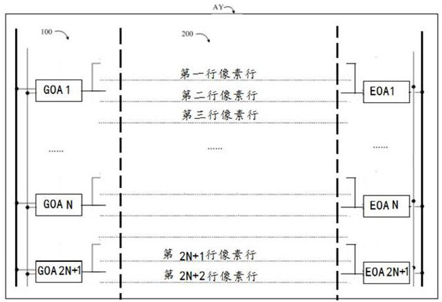
[0233] A scanning driving circuit shown according to an exemplary embodiment includes:
[0234] A plurality of the above-mentioned scan driving units.
[0235] It can be understood that, in the technical solution provided by this embodiment, since the improved scanning drive unit can output a normally low light emission control signal during the AGO phase when the gate lines are fully on, if the technical solution provided by this embodiment is applied to the The scanning drive of the OLED display is used in conjunction with the GOA drive unit that supports the AGO function in the prior art, so as to ensure that the display can display normally when the screen wakes up from a black screen.
PUM
 Abstract
Description
Claims
Application Information
 - R&D
- Intellectual Property
- Life Sciences
- Materials
- Tech Scout
- Unparalleled Data Quality
- Higher Quality Content
- 60% Fewer Hallucinations
Browse by: Latest US Patents, China's latest patents, Technical Efficacy Thesaurus, Application Domain, Technology Topic, Popular Technical Reports.
© 2025 PatSnap. All rights reserved.Legal|Privacy policy|Modern Slavery Act Transparency Statement|Sitemap|About US| Contact US: help@patsnap.com


