
Non-contact indirect excitation dual-purpose generator

A generator, non-contact technology, applied in the direction of friction generator, generator/motor, piezoelectric effect/electrostrictive or magnetostrictive motor, etc., can solve the restrictions on the popularization and application of self-powered sensor monitoring technology Avoid problems such as damage to the energy converter, wear and tear failure, and achieve the effects of high natural frequency and reliability, strong power generation capacity, and avoiding low-frequency resonance

Pending Publication Date: 2021-08-17
ZHEJIANG NORMAL UNIVERSITY
View PDF4 Cites 0 Cited by
  • Summary
  • Abstract
  • Description
  • Claims
  • Application Information

AI Technical Summary

Problems solved by technology

However, most of the existing piezoelectric generators generate power through contact excitation, and the transducer is easily damaged due to excessive impact at high speeds. The friction generator generates power through slipping, and is prone to failure due to friction and wear of the friction pair, which seriously restricts self-power supply. Popularization and Application of Sensing Monitoring Technology

Method used


Image

  • Non-contact indirect excitation dual-purpose generator
  • Non-contact indirect excitation dual-purpose generator
  • Non-contact indirect excitation dual-purpose generator

Examples


Embodiment Construction

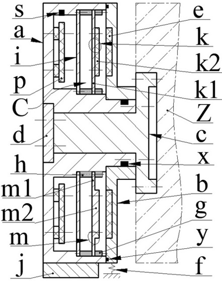
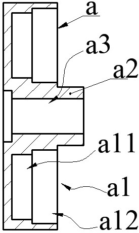
[0028] A dual-purpose generator with non-contact indirect excitation, which mainly consists of a casing a, an excitation disk b, a rotating shaft c, a stopper d, an excitation magnet e, a spring f or an inertia block j, a pressure ring g, a cavity ring h, and a transducer I, circuit board p, sensor s and coupler, the coupler is a magnetic coupler k or a non-magnetic coupler m; the rotating shaft c is installed on the rotating body Z, the casing a is set on the rotating shaft c, and the excitation disc b is set On the casing a, the excitation magnet e is installed on the excitation disk b, the sensor s, the circuit board p, the transducer i and the coupler are installed on the casing a, and the circuit board p is equipped with energy conversion and control circuits and transmitters. In the system, the transducer i and the sensor s are connected to the circuit board p through different wire groups; one of the housing a and the excitation disk b rotates with the rotating shaft c, ...


PUM


Abstract

The invention relates to a non-contact indirect excitation dual-purpose generator, and belongs to the field of new energy. A machine shell is provided with a stepped cavity composed of an inner cavity and an outer cavity and an inner shaft sleeve with an inner shaft hole. An excitation disc is composed of a disc body with an excitation magnet and an outer shaft sleeve with an outer shaft hole. The shaft sleeve is arranged on a rotating body, the inner shaft hole sleeves the rotating shaft, and the outer shaft hole sleeves the inner shaft sleeve; a transducer, a cavity ring and a coupler are arranged on the bottom wall of the outer cavity, the coupler is a magnetic coupler or a non-magnetic coupler, and the transducer is a piezoelectric transducer, a friction transducer or a piezoelectric-friction composite transducer; the transducer, the cavity ring and the coupler define a coupling cavity; one of the casing and the excitation disc rotates along with the rotating shaft, and the other is kept relatively static; when the machine shell and the excitation disc rotate relatively, the excitation magnet forces the transducer to bend and deform in a reciprocating mode through the coupler and the coupling cavity and converts mechanical energy into electric energy, the electric energy is stored or supplied to the sensor after being processed, and the sensor obtains relevant system parameters in real time and then transmits the relevant system parameters through the transmitting system.

Description

technical field [0001] The invention belongs to the technical field of new energy and power generation, and specifically relates to a dual-purpose generator with non-contact indirect excitation, which uses piezoelectricity and friction principles to recover the kinetic energy of a rotating body or fluid kinetic energy, and supplies power for a rotating body monitoring system and a river monitoring system. Background technique [0002] According to the data, the number of IoT sensors and devices put into use in the world may have increased from 100 to 200 million in 2016 to 26 billion in 2020. The information acquisition and exchange of IoT sensors and devices require continuous energy supply. If the battery is powered, it needs to be replaced frequently; if the cable is powered, the cost is high, the mobility is poor, and it is inconvenient to be used in rotating machinery and outdoor natural environments. Therefore, people have proposed micro-rotating generators with differ...

Claims


Application Information

Patent Timeline
IPC IPC(8): H02N1/04H02N2/18
CPCH02N1/04H02N2/18H02N2/185
Inventor 阚君武张李翟仕杰夏倩雯曹红兵程光明吴鸣曾平
Owner ZHEJIANG NORMAL UNIVERSITY
Learn More