
Moisture-proof device for water conservancy, hydropower and electrical automation equipment

A technology of electrical automation, water conservancy and hydropower, applied in the direction of gas treatment, chemical instruments and methods, separation methods, etc., can solve the problems of inability to achieve dehumidification effect, poor sealing performance of moisture-proof devices, etc., and achieve the effect of improving moisture-proof performance and ensuring airtightness

Active Publication Date: 2021-08-20
刘云博 +3
View PDF7 Cites 0 Cited by
  • Summary
  • Abstract
  • Description
  • Claims
  • Application Information

AI Technical Summary

Problems solved by technology

[0008] The object of the present invention is to provide a moisture-proof device for water conservancy, hydropower, electrical automation equipment, by making the gasket contact with the box door, and at the same time make the gasket and the box door have a certain pressure in the closed state of the box door to make the gasket and the box door When the desiccant is saturated with water, the heating wire is used to heat the desiccant to separate the moisture in the desiccant from the desiccant, and at the same time, the fan is used to discharge the moisture in the desiccant, which solves the problem of the existing technology. The sealing performance of the moisture-proof device is poor, and when the desiccant in the prior art absorbs the moisture in the cabinet environment and reaches saturation, the moisture in the desiccant cannot be discharged, causing the moisture to circulate inside the cabinet, and the dehumidification effect cannot be achieved. The problem

Method used


Image

  • Moisture-proof device for water conservancy, hydropower and electrical automation equipment
  • Moisture-proof device for water conservancy, hydropower and electrical automation equipment
  • Moisture-proof device for water conservancy, hydropower and electrical automation equipment

Examples


Embodiment Construction

[0034] The following will clearly and completely describe the technical solutions in the embodiments of the present invention with reference to the drawings in the embodiments of the present invention.

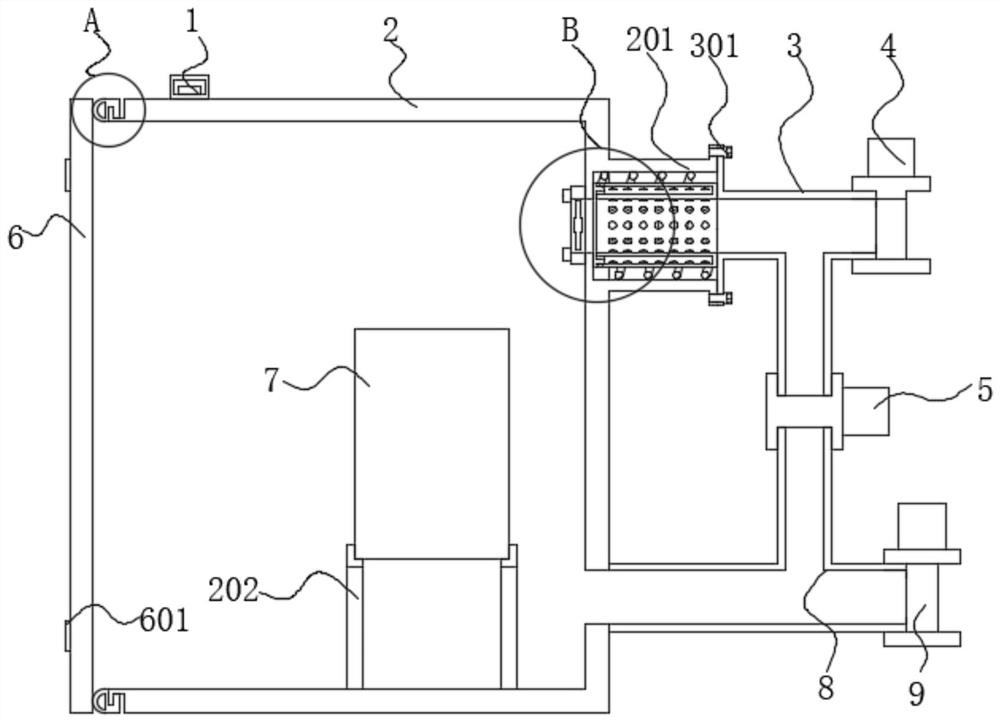
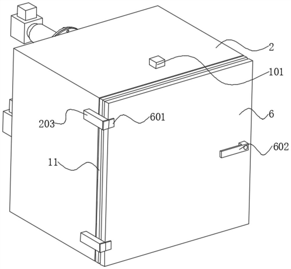
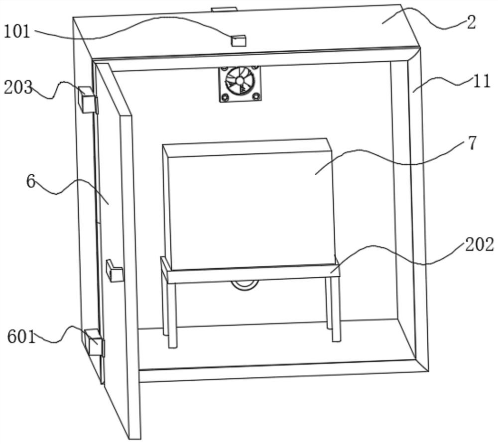
[0035] see Figure 1-9As shown, the present invention is a moisture-proof device for water conservancy, hydropower, electric automation equipment, including a box body 2, an equipment body 7 is arranged inside the box body 2, a single-chip microcomputer 1 is arranged on the front side of the upper wall of the box body 2, and the input terminal of the single-chip microcomputer 1 Electrically connected with the external power supply through conductive wires, a box door 6 is arranged in front of the box body 2, the rear wall of the box door 6 is a smooth plane, and a gasket 10 is arranged in front of the box body 2, and the gasket 10 is arranged in a circular shape. , and the sealing gasket 10 is located on the outside of the flange 204, the sealing gasket 10 is made of rubber ma...


PUM


Abstract

The invention discloses a moisture-proof device for water conservancy, hydropower and electrical automation equipment, and belongs to the technical field of water conservancy and hydropower engineering. The device comprises a box body, a sealing gasket is arranged in front of the box body, a heating wire is arranged outside a placement pipe, and a fan is fixed to the position, corresponding to the rear wall in the box body, of the placement pipe. According to the moisture-proof device, a sealing gasket is in contact with a box door, meanwhile, certain pressure exists between the sealing gasket and the box door in the closed state of the box door so that the sealing gasket can be attached to the box door; and under the condition that the moisture in a drying agent is saturated, the drying agent is heated through the heating wire so that the moisture in the drying agent can be separated from the drying agent, meanwhile, the fan is used for discharging the moisture in the drying agent, and therefore, the problem that a moisture-proof device is poor in sealing performance in can be solved.the prior art, when a drying agent absorbs moisture in the environment in a cabinet body and is saturated, the moisture in the drying agent cannot be discharged, the moisture circulates in the cabinet body, and the dehumidification effect cannot be achieved. With the moisture-proof device adopted, the above problem can be solved.

Description

technical field [0001] The invention belongs to the technical field of water conservancy and hydropower engineering, in particular to a moisture-proof device for electric automation equipment of water conservancy and hydropower. Background technique [0002] Water is the basic element that human beings depend on for survival, and electricity is the main energy source for social development. Water conservancy and hydropower engineering is an engineering science that regulates and utilizes water energy resources by engineering or non-engineering measures on the basis of the study of the natural characteristics of water. It is mainly engaged in The planning, design, construction, management and scientific research of large and medium-sized water conservancy and hydropower projects and their buildings (including dams, hydropower plant buildings, gates and water intake, water diversion, water discharge structures, etc.), as well as industrial hydraulic structures, in the field of ...

Claims


Application Information

Patent Timeline
IPC IPC(8): B01D53/26
CPCB01D53/26B01D2257/80
Inventor 刘云博李宏鑫郝红勋李宏硕
Owner 刘云博
Features
  • Generate Ideas
  • Intellectual Property
  • Life Sciences
  • Materials
  • Tech Scout
  • Unparalleled Data Quality
  • Higher Quality Content
  • 60% Fewer Hallucinations
Learn More