Inverse gravity filling forming device of large-size complex amorphous alloy component

An amorphous alloy and anti-gravity technology, which is applied in the field of anti-gravity filling and forming devices for large-scale and complex amorphous alloy components, can solve problems such as high viscosity, low flow performance, and difficulty in filling complete components.

Active Publication Date: 2021-08-20
HARBIN INST OF TECH
View PDF20 Cites 0 Cited by
  • Summary
  • Abstract
  • Description
  • Claims
  • Application Information

AI Technical Summary

Problems solved by technology

In addition, the bulk amorphous alloy has the characteristics of high viscosity, and its flow performance is extremely low under the condition of gravity field.
It is difficult to fill

Method used


Image

  • Inverse gravity filling forming device of large-size complex amorphous alloy component
  • Inverse gravity filling forming device of large-size complex amorphous alloy component
  • Inverse gravity filling forming device of large-size complex amorphous alloy component

Examples


specific Embodiment approach 2

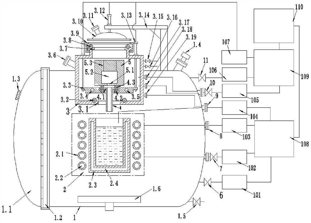
[0041] Specific implementation mode two: combination Figure 1-Figure 6 This embodiment is described. The large-scale and complex amorphous alloy component described in this embodiment is an anti-gravity filling and forming device. The melting chamber includes a melting chamber shell 1, a melting chamber door 1.1, a melting chamber locking ring assembly 1.2, and a melting chamber observation window 1.3 , The smelting cabin can adjust the camera 1.4 and the smelting cabin exhaust valve 1.5; the smelting cabin shell 1 is a cylindrical shell with one end open, the axis direction of the smelting cabin shell 1 is set horizontally, and the smelting cabin door 1.1 is locked through the smelting cabin The sealing cover of the ring assembly 1.2 is installed on the opening end of the smelting cabin shell 1, the smelting cabin observation window 1.3 is installed on the smelting cabin door 1.1, the smelting cabin adjustable camera 1.4 is installed on the top seal of the smelting cabin shel...

specific Embodiment approach 3

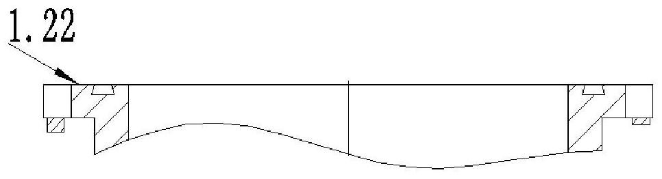
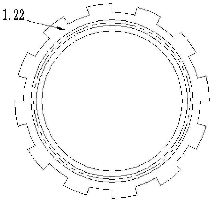
[0044] Specific implementation mode three: combination Figure 1-Figure 6 Describe this embodiment, the reverse gravity filling and forming device for large-scale complex amorphous alloy components described in this embodiment, the smelting cabin locking ring assembly 1.2 includes a smelting cabin locking ring 1.21, two locking flanges 1.22 and two locking Oil cylinder 1.23, a locking flange 1.22 is provided with sawtooth-shaped protrusions evenly distributed along the radial direction, the melting cabin locking ring 1.21 is an annular body, and the inner side wall of the annular body is processed with annular grooves in the radial direction, and the melting cabin locking ring 1.21 The side wall on one side is processed with a zigzag groove matching each zigzag protrusion on the locking flange 1.22, and another locking flange 1.22 is fixedly installed on the opening end of the melting cabin shell 1, and the melting cabin door 1.1 There is a locking flange 1.22 with saw-tooth-s...


PUM


Abstract

The invention discloses an inverse gravity filling forming device of a large-size complex amorphous alloy component, relates to an amorphous alloy casting device, and aims to provide equipment for ensuring the purity of a smelted alloy, overcoming gravity constraint filling casting and realizing relatively rapid solidification and cooling. The inverse gravity filling forming device comprises a smelting cabin, an induction heating system, an inverse gravity filling cabin, an inverse gravity filling riser tube, an amorphous component forming die and a computer control actuator. The smelting cabin is a sealed tank body, the induction heating system is arranged in the smelting cabin, the inverse gravity filling cabin is arranged above the induction heating system and is installed on a shell at the top of the smelting cabin in a sealed manner, the inverse gravity filling riser tube is installed at the bottom of the inverse gravity filling cabin, the amorphous component forming die is installed at the position, above the inverse gravity filling riser tube, in the inverse gravity filling cabin, and the induction heating system, the inverse gravity filling cabin, the inverse gravity filling riser tube and the amorphous component forming die all communicate with the computer control actuator. The invention belongs to the field of casting forming.

Description

technical field [0001] The invention relates to an amorphous alloy casting device, in particular to an anti-gravity filling forming device for a large-scale complex amorphous alloy component. Background technique [0002] In recent years, bulk non-alloy materials have been prepared in laboratories using small non-consumable electrodes and induction melting. However, due to the limitation of equipment conditions and the lack of suitable forming methods, it has not been effectively applied. At present, there are three major difficulties restricting the industrial production of such fine material products. First, although bulk amorphous alloys differ from the extremely high cooling rates required for conventional amorphous formation. However, relatively high cooling conditions are also required. When the cooling rate is lower than the critical cooling rate, the alloy will crystallize, and completely amorphous materials cannot be obtained. Traditional casting methods and ordi...

Claims


Application Information

Patent Timeline
IPC IPC(8): B22D18/00B22D18/08C22C1/02C22C33/04B22D27/04B22D27/15B22D27/00B22D35/04B22D35/06
CPCB22D18/00B22D18/08C22C1/02C22C33/003C22C33/04B22D27/04B22D27/15B22D27/003B22D35/04B22D35/06C22C1/11
Inventor 孙剑飞曹福洋姜思达黄永江沈红先张伦勇邱子傲宁志良
Owner HARBIN INST OF TECH
Why Eureka
Try Eureka