An open pipeline type screw conveying equipment

A screw conveying and pipeline-type technology, which is applied in the field of open pipe-type screw conveying equipment, can solve the problems of easy deterioration of conveying, easy blockage of materials, and low conveying efficiency, so as to reduce the probability of material accumulation or blockage, reduce waste rate, The effect of increasing the conveying speed

Active Publication Date: 2021-09-21
山东鹤鹏技术有限公司
View PDF18 Cites 0 Cited by
  • Summary
  • Abstract
  • Description
  • Claims
  • Application Information

AI Technical Summary

Problems solved by technology

[0003] The working principle of the screw conveyor is that the rotating helical blade pushes the material and conveys it in a screw. The screw conveyor is mainly used to transport various powdery, granular and small block materials. The bulk materials conveyed include grain, beans, Grain products such as flour, construction materials such as cement, clay, sand, chemicals such as salt, alkali, fertilizer, and bulk cargo such as coal, coke, ore, but not suitable for transporting perishable, viscous, and easy to condense At present, the following problems will occur during the screw conveying process of the material: the material is easy to block or accumulate in the conveying equipment, and the common conveying equipment lacks the function of synchronously cleaning the spiral blades, and at the same time, the spiral conveying equipment is during the horizontal conveying of materials. For materials with poor fluidity or certain viscosity, the overall conveying efficiency is low

Method used


Image

  • An open pipeline type screw conveying equipment
  • An open pipeline type screw conveying equipment
  • An open pipeline type screw conveying equipment

Examples


Embodiment Construction

[0030] In order to make the technical means realized by the present invention, creative features, goals and effects easy to understand, the following combination Figure 1 to Figure 7, to further elaborate the present invention.

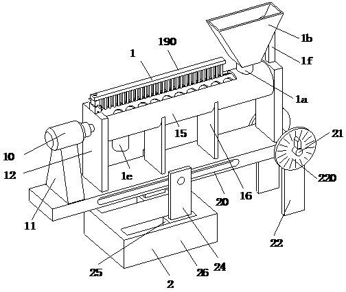
[0031] An open pipeline type screw conveying equipment includes a conveying mechanism 1 and an adjusting mechanism 2, the conveying mechanism 1 is arranged on the upper end of the adjusting mechanism 2, and the adjusting mechanism 2 is placed on the ground.

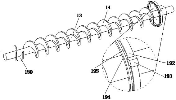
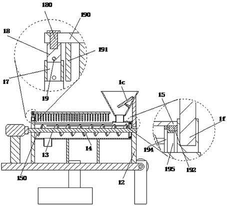
[0032] refer to figure 1 , figure 2 , image 3 and Figure 5 , the conveying mechanism 1 includes a motor 10, a base 11, a bracket 12, an intermediate shaft 13, a screw blade 14, a barrel 15, a support plate 16, a return block 17, a built-in block 18, a clamping shaft 19, a top plate 190 and elastic Rod 191, the base 11 is installed on the lower end of the motor 10, the left and right sides of the motor 10 are symmetrically arranged with brackets 12, the upper ends of the brackets 12 are ro...


PUM


Abstract

The invention relates to the field of screw conveying equipment. The invention provides an open pipeline type screw conveying equipment, which adopts the design concept of multi-control to carry out the spiral conveying of materials, and the whole equipment can realize the cleaning of its own interior on the basis of realizing material conveying At the same time, it can also play a certain role in evacuating the materials, thereby reducing the probability of material accumulation or blockage. The adjustment mechanism set can make the conveying mechanism turn from horizontal to inclined state, and the inclined state can increase the conveying speed of materials, which is beneficial to the equipment. To adapt to the transportation of materials with poor fluidity or certain viscosity, the helical direction of the helical piece in the present invention is opposite to that of the helical blade. Push to the right to make it fall from the outlet chute, thereby avoiding the phenomenon that some materials accumulate inside the left end of the barrel, reducing the waste rate of materials.

Description

technical field [0001] The invention relates to the field of screw conveying equipment, in particular to an open pipeline type screw conveying equipment. Background technique [0002] The screw conveyor is a kind of machine that uses the motor to drive the screw to rotate and push the material to achieve the purpose of conveying. It has the advantages of simple structure, small cross-sectional area, good sealing, convenient operation, easy maintenance, and convenient closed transportation. [0003] The working principle of the screw conveyor is that the rotating helical blade pushes the material and conveys it in a screw. The screw conveyor is mainly used to transport various powdery, granular and small block materials. The bulk materials conveyed include grain, beans, Grain products such as flour, construction materials such as cement, clay, sand, chemicals such as salt, alkali, fertilizer, and bulk cargo such as coal, coke, ore, etc. At present, the following problems wil...

Claims


Application Information

Patent Timeline
Patent Type & Authority Patents(China)
IPC IPC(8): B65G41/00B65G33/24B65G33/14B65G33/26B65G45/10B65G33/34
CPCB65G33/14B65G33/24B65G33/265B65G33/34B65G41/002B65G45/10
Inventor 王艳春
Owner 山东鹤鹏技术有限公司
Why Eureka
Try Eureka