
High-strength steel strand producing, manufacturing and stranding processing machine

A technology of high-strength steel and processing machinery, which is applied in the direction of textiles, papermaking, rope-making auxiliary devices, textile cables, etc., and can solve the problems of uneven angles between steel wires, poor stranding quality, and poor polymerization of steel strands, etc. problems, to achieve the effect of improving stranding quality, improving overall performance, and improving accuracy

Inactive Publication Date: 2021-08-20
武亮
View PDF9 Cites 2 Cited by
  • Summary
  • Abstract
  • Description
  • Claims
  • Application Information

AI Technical Summary

Problems solved by technology

[0005] The present invention can solve the following problems that existing equipment may encounter in the process of stranding steel wires: a. During the stranding process of steel wires, due to the large number of wire bundles of steel wires, it is difficult for traditional stranding equipment to The positioning, installation and guiding function of the steel wire coil will cause the steel wire to be easily entangled during the stranding process, resulting in the problem of stranding being blocked or poor stranding quality, resulting in the unusable steel strand after stranding ; b. The installation position of the steel wire coils is mostly fixed, so that when adjusting the stranding of steel wires with different strands, the installation position of the steel wire coils cannot be changed, resulting in different angles between the twisted steel wires. uniform, resulting in a poor degree of polymerization of the stranded steel strands, thereby reducing the overall performance of the steel strands

Method used


Image

  • High-strength steel strand producing, manufacturing and stranding processing machine
  • High-strength steel strand producing, manufacturing and stranding processing machine
  • High-strength steel strand producing, manufacturing and stranding processing machine

Examples


Embodiment Construction

[0035] The embodiments of the present invention will be described in detail below with reference to the accompanying drawings, but the present invention can be implemented in many different ways defined and covered by the claims.

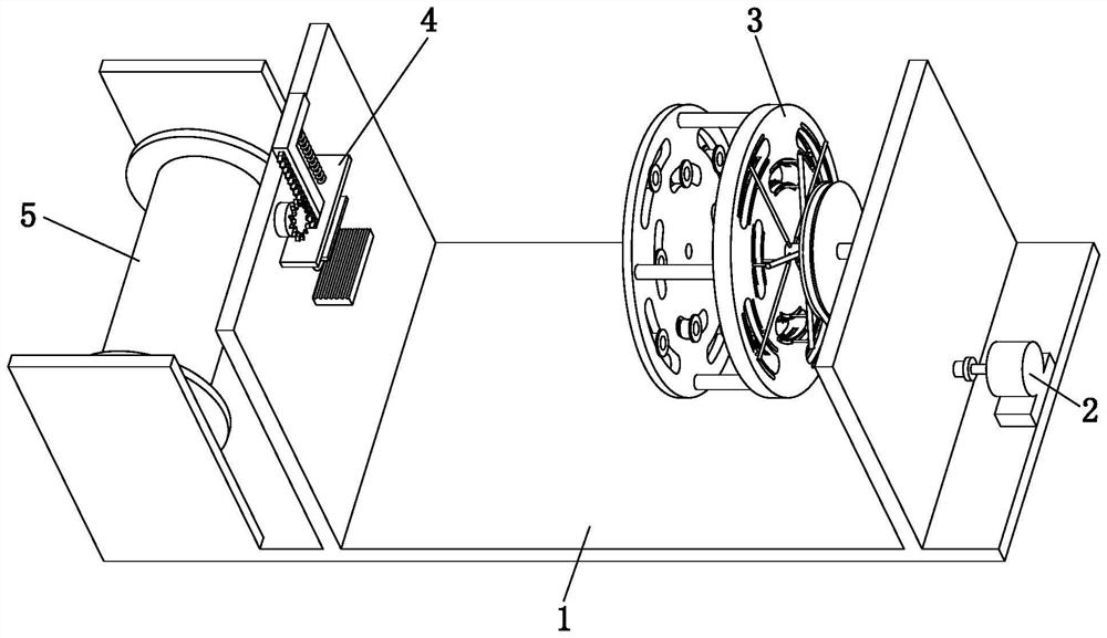
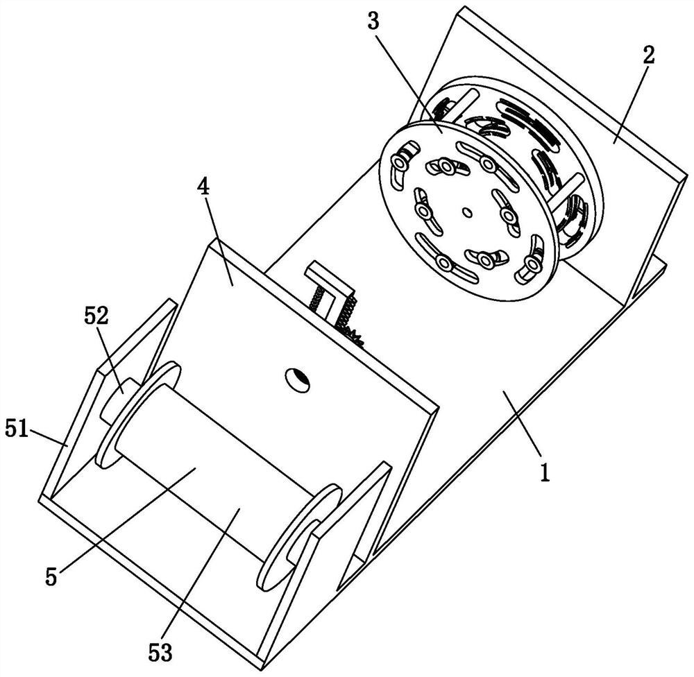
[0036] Such as Figure 1 to Figure 11As shown, a high-strength steel strand production and manufacturing stranding processing machine includes a base plate 1, a driving device 2, a stranding device 3, a clamping device 4 and a winding device 5, and the right end of the upper end surface of the base plate 1 is set There is a driving device 2, the left end of the driving device 2 is fixedly connected with a twisting device 3, the left side of the twisting device 3 is provided with a clamping device 4, and the left side of the clamping device 4 is equipped with a winding device 5, wherein:

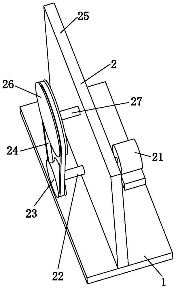
[0037] Described driving device 2 comprises drive motor 21, drive shaft 22, driving pulley 23, endless belt 24, first mounting plate 25, driven pulley 26 and rotat...


PUM


Abstract

The invention relates to a high-strength steel strand producing, manufacturing and stranding processing machine. The high-strength steel strand producing, manufacturing and stranding processing machine comprises a bottom plate, a driving device, a stranding device, a clamping device and a winding device. The stranding processing machine can solve the following problems in the stranding process of steel wires: a, the number of wire harnesses of the steel wires is relatively large, traditional stranding equipment cannot position, install and guide steel wire coils easily, so that the phenomenon that the steel wires are wound easily in the stranding process is caused, consequently, the stranding is blocked or the stranding quality is relatively poor, and the stranded steel strands cannot be put into use; and b, the mounting positions of the steel wire coils are mostly fixed, so that when different strands of steel wires are stranded and adjusted, the mounting positions of the steel wire coils cannot be changed, the included angles between the stranded steel wires are not uniform, the polymerization degree of the stranded steel strands is relatively poor, and the overall performance of the steel strands is reduced.

Description

technical field [0001] The invention relates to the field of manufacturing and stranding of high-strength steel strands, in particular to a manufacturing and stranding processing machine for high-strength steel strands. Background technique [0002] High-strength steel strand is a bundle of steel wires twisted and twisted with multiple steel wires. The surface of carbon steel can be added with galvanized layer, zinc-aluminum alloy layer, aluminum-clad layer, copper-plated layer, and epoxy resin coating as required. Wait. High-strength steel strands are mostly twisted by a stranding machine during production, and the twisted steel strands are wound up through an I-shaped wheel. [0003] At present, the existing equipment may encounter the following difficulties in the process of stranding the steel wires: a. During the stranding process of the steel wires, due to the large number of wire bundles of the steel wires, it is difficult for the traditional stranding equipment to s...

Claims


Application Information

Patent Timeline
IPC IPC(8): D07B3/02D07B7/06D07B7/10D07B7/02
CPCD07B3/02D07B7/06D07B7/10D07B7/02
Inventor 武亮
Owner 武亮
Learn More