Construction method of high pressure mud retaining wall with underground diaphragm wall forming groove

A technology for underground diaphragm walls and mud retaining walls, which is applied in excavation, infrastructure engineering, construction, etc., can solve problems such as increased consumption, difficult separation of formation particles, and limited reinforcement depth, so as to achieve improved reliability, high sealing reliability, and reduced The effect of construction costs

Active Publication Date: 2022-07-15
江苏中车城市发展有限公司 +2
View PDF5 Cites 0 Cited by
  • Summary
  • Abstract
  • Description
  • Claims
  • Application Information

AI Technical Summary

Problems solved by technology

Increasing the mud proportion of the retaining wall is an important means to control the deformation of the groove wall and improve its stability, but when the mud proportion increases, the mud fluidity will become poor, which will increase the power consumption of the mud circulation equipment, and at the same time, the formation particles carried by the mud will also be more It is difficult to be separated, and it will also affect the pouring of concrete; the reinforcement of the groove wall is to reinforce the groove wall with cement mixing piles before the groove is formed, so as to improve the stability of the groove wall and control the deformation of the groove wall, but the reinforcement of the groove wall Higher cost, in addition, the reinforcement depth of the groove wall reinforcement is relatively limited

Method used


Image

  • Construction method of high pressure mud retaining wall with underground diaphragm wall forming groove
  • Construction method of high pressure mud retaining wall with underground diaphragm wall forming groove
  • Construction method of high pressure mud retaining wall with underground diaphragm wall forming groove

Examples


Embodiment 1

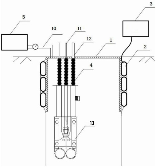
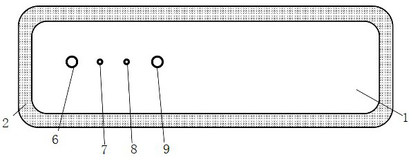
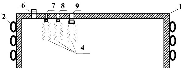
[0031] like Figure 1 to Figure 3 As shown in the figure, a method for constructing a high-pressure mud retaining wall in which an underground diaphragm wall is formed into a groove is characterized by comprising the following steps:

[0032] A. Forming the guide wall; before the underground continuous wall is constructed into a groove, the guide wall shall be constructed according to the specification requirements; if the deformation modulus of the soil body within 2 meters below the guide wall is low, the soil body shall be carried out along the guide wall before the guide wall is constructed. reinforcement.

[0033] B. Install the slot milling machine 13; both the suspension line 11 and the pulp outlet pipe 12 of the slot milling machine 13 pass through the reserved holes of the sealing device, and the suspension wire and the pulp outlet tube of the slot milling machine are placed on the slot milling machine 13 to guide The upper part of the frame; the suspension wire 11 p...

Embodiment 2

[0042] A method for constructing a high-pressure mud retaining wall in which an underground diaphragm wall is formed into a groove, such as Figure 4 As shown, the difference between Embodiment 2 and Embodiment 1 is that the end of the telescopic sealing sleeve 4 is provided with an annular connecting convex portion, and the annular connecting convex portion is connected with the corresponding equipment through screws. The annular connecting convex portion includes an annular folded surface 41 integral with the upper end of the telescopic sealing sleeve 4 , and the shape of the axial cross-section of the annular folded surface 41 is “M” shape. The outer end of the annular folding surface 41 is provided with a sealing edge 42 arranged around the outer end of the annular folding surface 41, and the shape of the sealing edge 42 is an "S" shape in cross-section; 4. The sealing lip 43 of the plane where the upper end is located.

Embodiment 3

[0044] A method for constructing a high-pressure mud retaining wall in which an underground diaphragm wall is formed into a groove, such as Figure 5 As shown, the difference between Embodiment 3 and Embodiment 1 is that: the slurry pipe 14 of the slot milling machine 13 is provided with a flat pressing hole 141, the flat pressing hole 141 is provided with an elastic film 142, and the flat pressing hole 141 is provided with a peripheral There is a flat pressure pipe 143 , a flat pressure column 144 is arranged in the flat pressure pipe 143 , a limit cap 145 is arranged at the outer end of the flat pressure column 144 , and an elastic reset member is arranged between the limit cap 145 and the slurry outlet pipe 14 . There is a flow cycle of slurry inlet and outlet in the groove, and the flowing slurry will cause the pressure difference between the slurry inlet and the slurry outlet. The slurry outlet pipe 14 of the milling machine 13 is located between the slurry inlet hole 6 a...


PUM


Abstract

The invention discloses a method for constructing a high-pressure mud retaining wall for forming a groove into an underground continuous wall, comprising the following steps: forming a guide wall; installing a groove milling machine; ; until the entire groove section is grooved. The advantages of the invention are that it can control the pressure of the mud in the groove, and use the sealing device of the groove and the hydraulic pump to realize the high-pressure retaining wall of the mud during the forming of the groove, so as to limit the lateral deformation of the soil body of the groove wall, thereby reducing the construction of the underground continuous wall. The construction cost of milling into the groove is simple and efficient; the sealing reliability of both ends of the telescopic sealing sleeve is high, which further improves the reliability of the high-pressure protective wall.

Description

technical field [0001] The present application relates to the technical field of forming grooves for underground diaphragm walls, and in particular, to a construction method for high-pressure mud retaining walls for forming grooves for underground diaphragm walls. Background technique [0002] With the rapid development of underground development and underground rail transit in China, the depth of support for underground excavation projects has gradually deepened, and underground diaphragm walls have become an important form of excavation support, especially for some deep excavation and surrounding For projects with high requirements for soil deformation, underground diaphragm walls have become the preferred form of support due to their good support characteristics. However, for the underground diaphragm wall, it is necessary to carry out trough construction under the condition of mud retaining wall. The deformation and stability of the trough wall during the trough formatio...

Claims


Application Information

Patent Timeline
Patent Type & Authority Patents(China)
IPC IPC(8): E02D17/08E02D15/00E02F5/02
CPCE02D17/08E02D15/00E02F5/02E02D2300/0023
Inventor 刘德欣武相坤朱春柏林强王浩刘伟苏光旭刘念武
Owner 江苏中车城市发展有限公司
Why Eureka
Try Eureka