An Active Suppression Method for Flutter of Engine Compression System Components

A compression system and active suppression technology, which is applied in the direction of machines/engines, liquid fuel engines, pumping devices for elastic fluids, etc., can solve the problem of reducing the stable working range of various engine components and difficult aeroelastic risk elimination , affecting the life of the engine and other issues, to achieve the effect of reducing the risk of flutter, improving the stability of flutter, and improving the problem of flutter

Active Publication Date: 2022-05-20
INST OF ENGINEERING THERMOPHYSICS - CHINESE ACAD OF SCI
View PDF9 Cites 0 Cited by
  • Summary
  • Abstract
  • Description
  • Claims
  • Application Information

AI Technical Summary

Problems solved by technology

It is difficult to completely eliminate aeroelastic risks such as flutter at the design stage, especially for civil fans with large bypass ratios
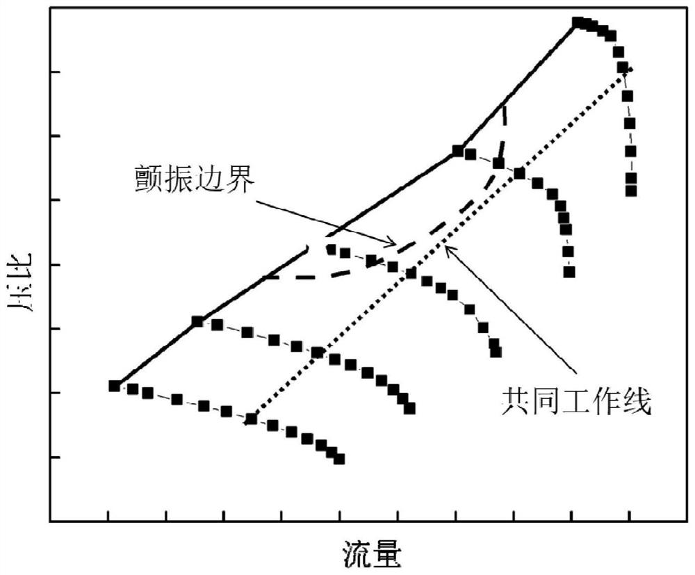
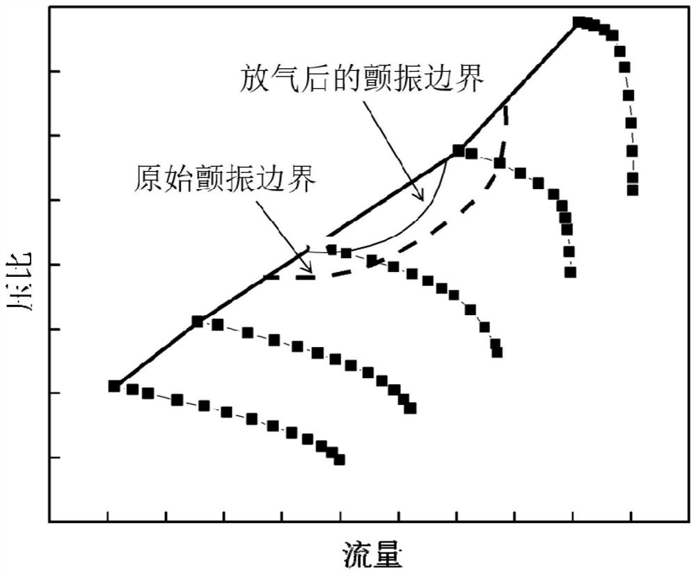
The flutter boundary often appears within the aerodynamic boundary. Although flutter does not appear in all speed conditions, the erosion of the aerodynamic boundary by the local flutter boundary will greatly reduce the stable working range of the engine components.
With blade wear, dust accumulation, icing and other phenomena, the high-load common working line is likely to enter the flutter boundary, affecting the life of the engine and threatening flight safety.

Method used


Image

  • An Active Suppression Method for Flutter of Engine Compression System Components
  • An Active Suppression Method for Flutter of Engine Compression System Components
  • An Active Suppression Method for Flutter of Engine Compression System Components

Examples


Embodiment Construction

[0034] In order to make the objectives, technical solutions and advantages of the present invention clearer, the technical solutions in the embodiments of the present invention will be described in more detail below with reference to the accompanying drawings in the embodiments of the present invention. The described embodiments are a part of the embodiments of the present invention, but not all of the embodiments, and are intended to be used to explain the present invention and should not be construed as a limitation of the present invention. Based on the embodiments of the present invention, all other embodiments obtained by those of ordinary skill in the art without creative efforts shall fall within the protection scope of the present invention.

[0035] In order to avoid flutter problems that threaten flight safety during engine operation, the present invention provides a flutter suppression method for compression system components that are prone to flutter problems. The ...


PUM


Abstract

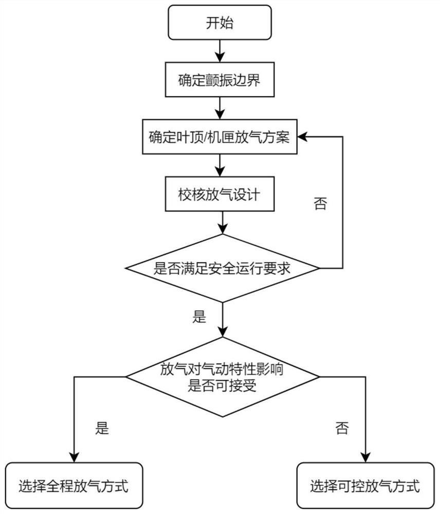
The invention belongs to the technical field of aero-engine compression systems, and relates to an active suppression method for the flutter of engine compression system components, which is mainly based on blade top / casing deflation, combined with non-contact blade vibration monitoring, without changing the original blade blade. On the basis of the model, the flutter occurrence area is reduced, and the safe working range of the engine is widened, so as to better improve the flutter problem of the compression system components and reduce the risk of flutter. Therefore, the impact on aerodynamic performance is very small. And the impact on aerodynamic performance can be further reduced by selecting a deflation structure that can be actively switched.

Description

technical field [0001] The invention belongs to the technical field of aero-engine compression systems, and relates to a method for suppressing the flutter of components of an engine compression system, in particular to a method for actively suppressing the flutter of components of an aero-engine compression system, which can better improve the flutter problem of components of the compression system. , reduce the risk of flutter, and have little impact on the aerodynamic performance of the system. Background technique [0002] Aero-engine blade flutter is an aeroelastic instability phenomenon that needs to be avoided during flight. This phenomenon often occurs in compression system components such as fans and low-pressure compressors. Flutter can lead to high-cycle blade fatigue even in a short period of time. Broken leaves. It is difficult to completely eliminate aeroelastic risks such as flutter in the design stage, especially for large bypass ratio civil fans. The flutt...

Claims


Application Information

Patent Timeline
Patent Type & Authority Patents(China)
IPC IPC(8): F04D29/66F04D27/00F04D27/02F04D29/26F04D29/40F02C9/18
CPCF04D29/668F04D27/001F04D27/0207F04D29/26F04D29/403F02C9/18Y02T90/00
Inventor 董旭张燕峰甘久亮卢新根
Owner INST OF ENGINEERING THERMOPHYSICS - CHINESE ACAD OF SCI
Why Eureka
Try Eureka