Three-dimensional dynamic column plate

A dynamic, tray technology, applied in distillation separation, chemical/physical/physical-chemical process, fractional distillation, etc., to improve the effect of gas-liquid separation, reduce pressure drop, and reduce foaming

Pending Publication Date: 2021-08-24
TIANJIN PULAITE SCI & TECH DEV +1
View PDF1 Cites 1 Cited by
  • Summary
  • Abstract
  • Description
  • Claims
  • Application Information

AI Technical Summary

Problems solved by technology

However, the above-mentioned compound injection tray is a fixed part, which is only suitable for working conditions with high gas velocity

Method used


Image

  • Three-dimensional dynamic column plate
  • Three-dimensional dynamic column plate
  • Three-dimensional dynamic column plate

Examples


Embodiment 1

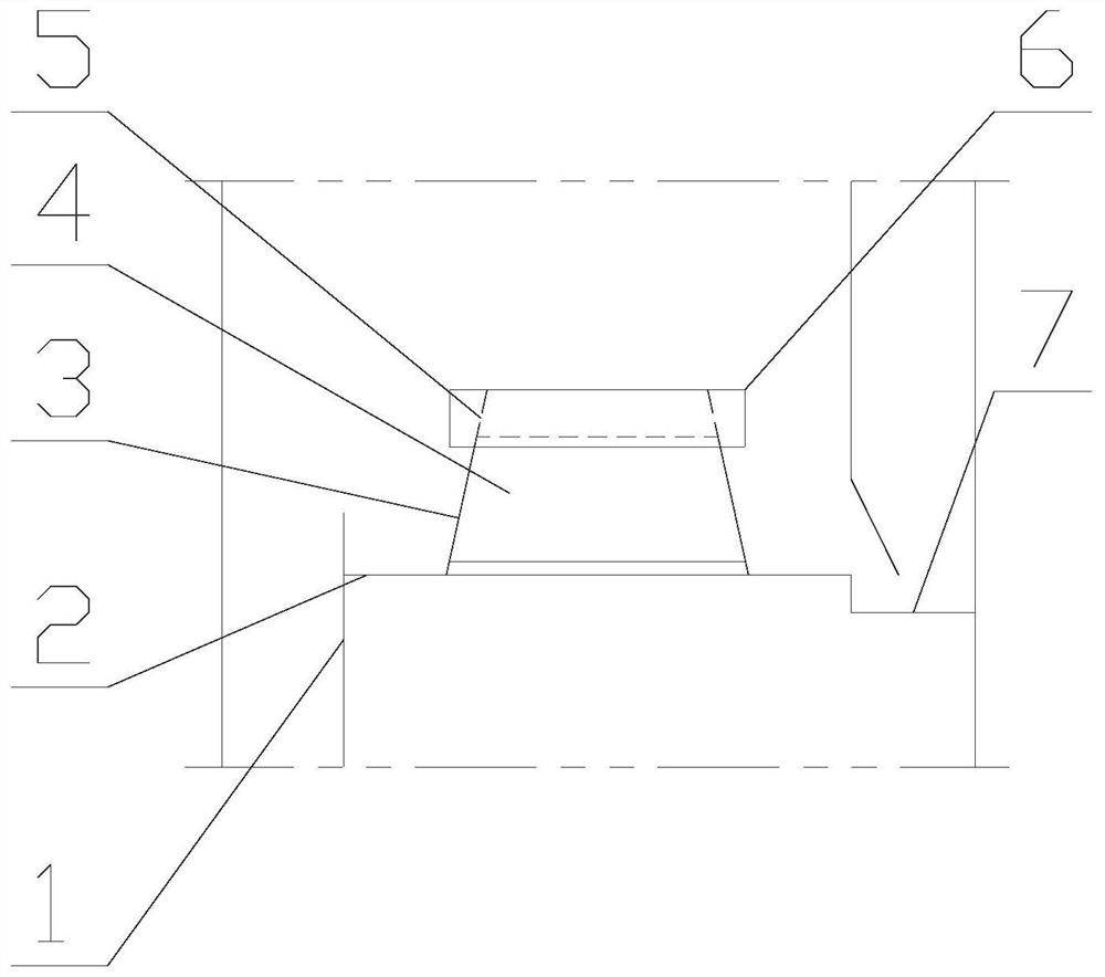
[0044] As shown in the figure, the three-dimensional dynamic tray of the present invention includes a tray 2, a downcomer plate 1, a liquid receiving tray 7 and a three-dimensional dynamic mass transfer unit installed on the tray 2, and the tray 2 is provided with a lift An air hole, the three-dimensional dynamic mass transfer unit is arranged above the air hole.

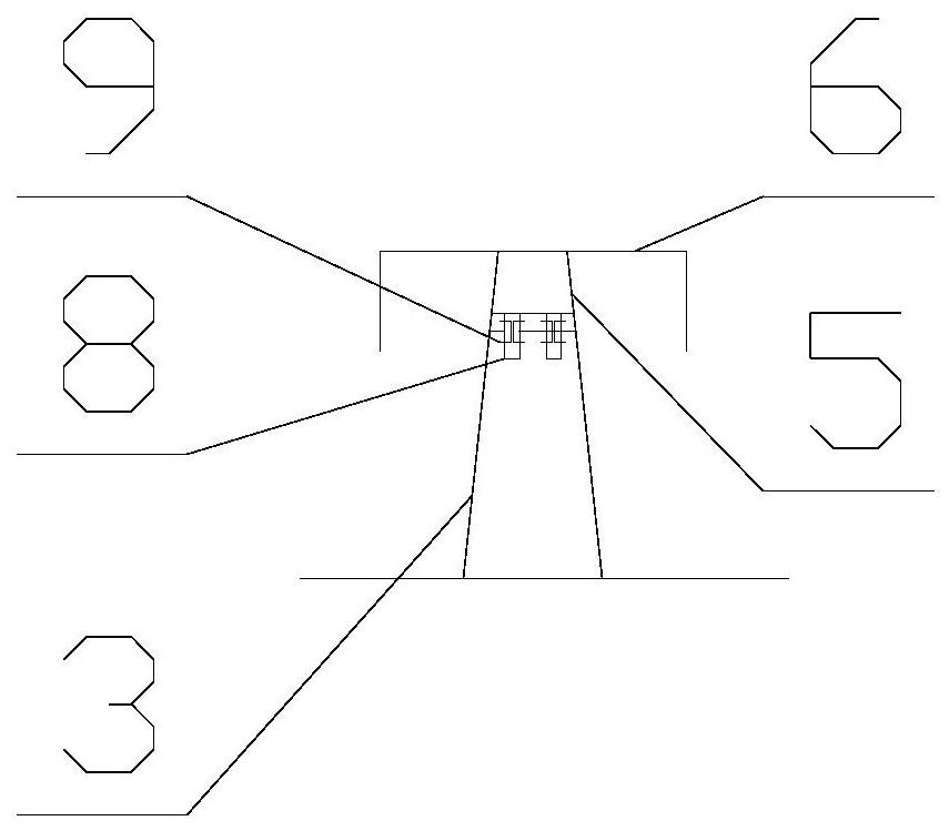
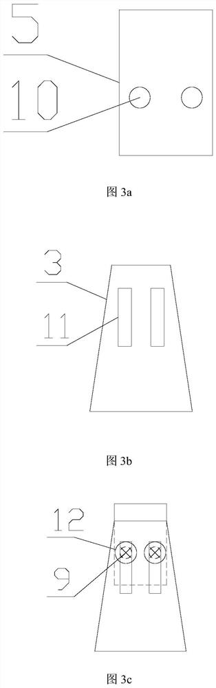
[0045] The three-dimensional dynamic mass transfer unit comprises a fixed end plate 3, a movable end plate 5, a spray plate 4 and a separation plate 6, the bottom of the fixed end plate 3 is installed on the column plate 2, the fixed end plate 3, the movable end plate Plate 5, the sides of spray plate 4 and the upper end of separation plate 6 encircle and form a spray channel, and said spray plate 4 is arranged on the side of fixed end plate 3, and said fixed end plate 3 is movably connected with movable end plate 5, so The top of the movable end plate 5 is connected with the separation plate 6, and there is an uppe...

Embodiment 2

[0055] Such as Figure 4 As shown, the three-dimensional dynamic tray of the present invention includes a tray 2, a downcomer plate 1, a liquid receiving tray 7 and a three-dimensional dynamic mass transfer unit installed on the tray 2, and the tray 2 is provided with a vent hole, The three-dimensional dynamic mass transfer unit is arranged above the air hole.

[0056] The three-dimensional dynamic mass transfer unit comprises a fixed end plate 3, a movable end plate 5, a spray plate 4 and a separation plate 6, the bottom of the fixed end plate 3 is installed on the column plate 2, and the edges of the fixed end plate 3, the movable The edge of the end plate 5, the side of the injection plate 4 and the upper end of the separation plate 6 enclose the injection channel, and the injection channel is trapezoidal. The injection plate 4 is arranged on the side of the fixed end plate 3, and the fixed end plate 3 and the The movable end plate 5 is movably connected, and the top of th...

Embodiment 3

[0063] Such as Figure 5 As shown, the three-dimensional dynamic tray of the present invention includes a tray 2, a downcomer plate 1, a liquid receiving tray 7 and a three-dimensional dynamic mass transfer unit installed on the tray 2, and the tray 2 is provided with a vent hole, The three-dimensional dynamic mass transfer unit is arranged above the air hole.

[0064] The three-dimensional dynamic mass transfer unit comprises a fixed end plate 3, a movable end plate 5, a spray plate 4 and a separation plate 6, the bottom of the fixed end plate 3 is installed on the column plate 2, and the edges of the fixed end plate 3, the movable The edge of the end plate 5, the side of the injection plate 4 and the upper end of the separation plate 6 enclose the injection channel, and the injection channel is circular. The injection plate 4 is arranged on the side of the fixed end plate 3, and the fixed end plate 3 It is movably connected with the movable end plate 5, and the top of the m...


PUM


Abstract

The invention discloses a three-dimensional dynamic column plate which comprises a column plate and a three-dimensional dynamic mass transfer unit mounted on the column plate, wherein each three-dimensional dynamic mass transfer unit comprises a fixed end plate, a movable end plate, an injection plate and a separation plate; the bottom of the fixed end plate is mounted on the column plate, an injection channel is defined by the edge of the fixed end plate, the edge of the movable end plate, the side edge of the injection plate and the upper end of the separation plate, the injection plate is arranged on the side edge of the fixed end plate, and a movable groove is formed in the fixed end plate; a fixed part matched with the movable groove is formed at the lower part of the movable end plate and is used for moving up and down in the movable groove, the top of the movable end plate is connected with the separation plate, a gap is reserved between the separation plate and the upper part of the injection plate, and a lower gap is reserved between the lower part of the injection plate and the column plate. Compared with a traditional column plate, the operation flexibility of the column plate is improved to 30-200%; wherein the movable end plate moves up and down relative to the fixed end plate, so that the distance between the separation plate and the spraying plate is adjusted, the gas-liquid separation effect is improved, and the suitable operation range is wider.

Description

technical field [0001] The invention belongs to the field of mass transfer and heat transfer equipment in chemical engineering, and in particular relates to a three-dimensional dynamic tray. Background technique [0002] Tray tower is an important gas-liquid mass transfer equipment in chemical production, and its interior is composed of tray, downcomer plate, liquid receiving plate, support ring, support plate, overflow weir and so on. The mass transfer unit of the plate tower tray can be designed as sieve holes, floating valves, solid valves, vertical sieve trays, three-dimensional mass transfer trays, etc. [0003] As an important component of mass transfer equipment, trays are widely used in chemical separation operations. For a long time, people have focused on the development of individual mass transfer components, and there have been various forms of trays named after individual components, such as sieve holes, bubble caps, float valves, and improved on this basis. G...

Claims


Application Information

Patent Timeline
IPC IPC(8): B01J19/32B01D3/16B01D3/32
CPCB01D3/16B01D3/324B01J19/32
Inventor 孙立军巢飞李柏春李春利
Owner TIANJIN PULAITE SCI & TECH DEV
Why Eureka
Try Eureka