Automatic gluing device

A gluing device and automatic technology, which is applied to the surface coating liquid device, coating, etc., can solve the problems of difficult control of gluing quality, high labor intensity, and low work efficiency, so as to achieve better gluing effect, Improve production efficiency and good practicability

Pending Publication Date: 2021-08-24
无锡钛达智能设备有限公司
View PDF0 Cites 0 Cited by
  • Summary
  • Abstract
  • Description
  • Claims
  • Application Information

AI Technical Summary

Problems solved by technology

[0003] Aiming at the disadvantages of manual surface gluing repair in the above-mentioned prior art, such as high labor intensity, low work efficiency, and difficulty in controlling the quality of gluing, the applicant provides an automatic gluing device with a reasonable structure, which can realize Mechanical automation operation, with the advantages of automatic gluing, quality control, good gluing effect, high work efficiency, etc.

Method used


Image

  • Automatic gluing device
  • Automatic gluing device
  • Automatic gluing device

Examples


Embodiment 1

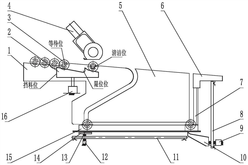
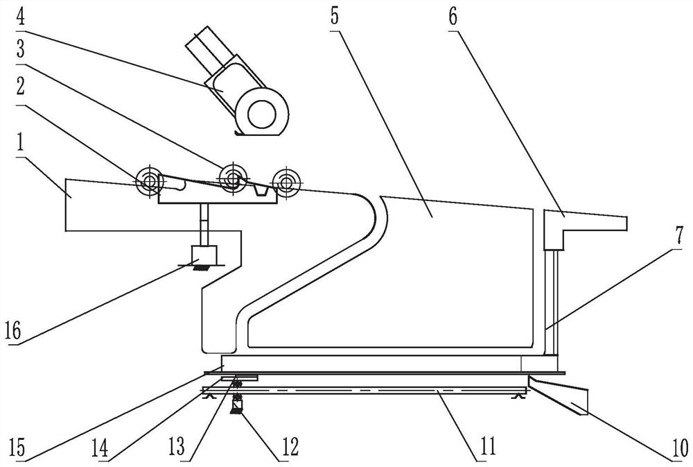
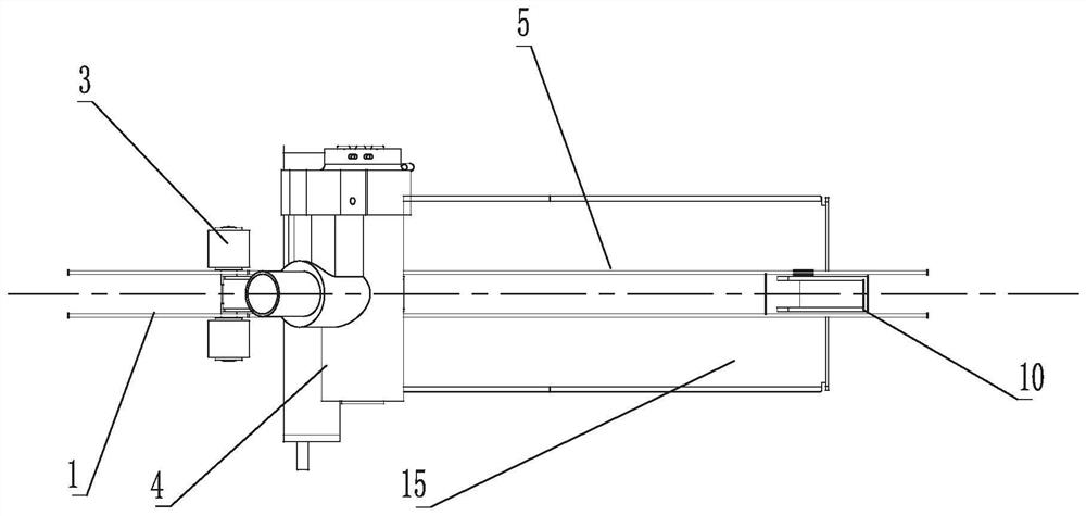
[0028] like Figure 1 to Figure 6 As shown, the automatic gluing device of the present invention is provided with glue box 15 on the frame, and glue box 15 is made of two square boxes arranged side by side in parallel, there is a certain interval between the two square boxes, and the top roller 3 can be placed Scroll horizontally in a straight line on two square boxes. The sponge and the cloth layer covering the sponge are placed in each square box. The square box is equipped with a liquid inlet, through which a certain volume of glue liquid is injected into the square box. The square box also has an overflow port, and the overflow port will exceed the The glue liquid of the set capacity is discharged, and the volume of the glue liquid in the square box remains unchanged. One end position below the glue box 15 is provided with a magnet block 13, and the magnet block 13 is controlled by a magnet drive mechanism to slide linearly along the length direction of the glue box 15. ...

Embodiment 2

[0039] As another embodiment, the difference between Embodiment 2 and Embodiment 1 lies in that the structure of the top roller feeding device is different. Specifically, a top roller feeding device is provided above the glue box. The top roller feeding device includes a feed raceway plate and an intermediate raceway plate. As for the vertical discharge device at the tail end of the glue box, it can be replaced by other ways to take out the top rollers. Moreover, the discharge raceway plate can also be replaced by other means, as long as the top roller needs to be taken out at the tail end of the glue box, it is no longer limited to the vertical discharge device and the discharge raceway plate of Embodiment 1. The matching relationship between the feed raceway plate and the top roller ejection frame remains unchanged.

Embodiment 3

[0041] As another embodiment, the difference between Embodiment 3 and Embodiments 1 and 2 lies in that the structure of the top roller feeding device is different. Specifically, a top roller feeding device is arranged above the glue box, and the top roller feeding device includes a feed raceway plate, and the two veneer tops of the feed raceway plate form the raceway of the top rollers, and the contours of the two veneer tops It consists of two inclined raceways at the front and rear. The end of the rear raceway is located above the beginning of the glue box, and the top roller directly enters the beginning of the glue box after passing through the rear raceway. The matching relationship between the feed raceway plate and the top roller ejection frame remains unchanged.


PUM


Abstract

The invention discloses an automatic gluing device. A glue box is arranged on a rack, a leather roller is placed on the glue box, a certain volume of glue liquid is injected into the glue box, a magnet block is arranged at one end of the lower portion of the glue box, the magnet block is controlled by a magnet driving mechanism to linearly move in the length direction of the glue box to drive the leather roller on the glue box to linearly roll, the leather roller rolls to the tail end of the glue box from the glue starting end of the glue box, and is coated with glue in the rolling process. Mechanical control is adopted, automatic operation is achieved, manual work is replaced, the production efficiency is remarkably improved, the leather roller gluing repairing quality is controllable, and the gluing effect is better. A sponge and a cloth layer covering the sponge are placed in the glue box, and the glue box is provided with a liquid inlet and an overflow port, so that a certain volume of glue liquid is kept in the glue box, and the glue box is long in service time, convenient in structure, free of manual guarding and better in practicability.

Description

technical field [0001] The invention relates to the technical field of textile machinery and equipment, in particular to an automatic gluing device for textile top rollers. Background technique [0002] The top roller is one of the important parts of the traction device of the textile machine. The top roller is characterized by an iron core with bearings at both ends in the middle, and a rubber roller with a rotatable outer diameter larger than the outer diameter of the iron core is installed on the bearings at both ends. . During spinning, cot rollers undertake the tasks of twisting, stretching and conveying yarn, and are used in a large amount. The performance of cot rollers has a decisive impact on spinning efficiency and yarn quality. Due to the long-term continuous pressure and scraping of the yarn on the surface of the yarn delivery cot, after a period of use, the surface of the cot will inevitably be damaged. The most common is the appearance of grooves on the surfac...

Claims


Application Information

Patent Timeline
Patent Type & Authority Applications(China)
IPC IPC(8): B05C3/10B05C9/10B05C13/02B05C11/11
CPCB05C3/10B05C9/10B05C11/11B05C13/02
Inventor 蒋柯屠晓峰林栋
Owner 无锡钛达智能设备有限公司
Why Eureka
Try Eureka