
Energy-saving glue coating machine for stone machining

A technology of stone processing and gluing machine, which is applied in the direction of coating and surface coating liquid device, etc., which can solve the problems of high maintenance cost, waste of glue, and cumbersome process, so as to improve the gluing process and effect and reduce work Good process and gluing effect

Inactive Publication Date: 2021-12-31
连云港奥林匹亚石材有限公司
View PDF4 Cites 0 Cited by
  • Summary
  • Abstract
  • Description
  • Claims
  • Application Information

AI Technical Summary

Problems solved by technology

[0002] Patent application number: 202010522612.2, which discloses a gluing device for stone processing. In this invention, a vertical plate, a straight groove, a first arc-shaped groove, and a second arc-shaped groove are set, and the length of the straight groove is set as the glue-coating length. The component drives the moving column to slide on the inner wall of the second arc-shaped groove, straight groove and first arc-shaped groove in sequence, and correspondingly moves the gluing head down to approach the stone, and the bottom of the gluing head touches the stone for gluing, and the gluing is completed After moving up and away from the stone, it is not convenient for side gluing. The existing stone gluing device cannot meet the side gluing or the effect of side gluing is not good. In the process of use, the glue needs to be stirred and poured into the kettle body , the process is cumbersome and wastes materials
[0003] Stone is often used in various places in life. In the process of stone processing, the stone is often glued. The existing glue coating equipment needs to stir the glue in advance and then pour it into the cavity. This kind of machine is not only The waste of glue is serious, and the glue outlet will be blocked for a long time. It is difficult to deal with the glue hanging on the wall of the cavity. It is also extremely troublesome to deal with the waste glue remaining on the operation table during the glue application process. The existing glue application equipment has a complicated structure. The stone to be glued needs to be clamped multiple times, and the glue applicator needs to be driven by a variety of components to apply glue. Its structure is complex and costly, and it is prone to failure. Robots and various complex components are required for coating. Glue, the above all lead to the high cost of gluing equipment in the prior art, more maintenance costs, and the need for multiple clamping for stone gluing

Method used


Image

  • Energy-saving glue coating machine for stone machining
  • Energy-saving glue coating machine for stone machining
  • Energy-saving glue coating machine for stone machining

Examples


Embodiment 1

[0028] Such as Figure 1-Figure 11 Shown:

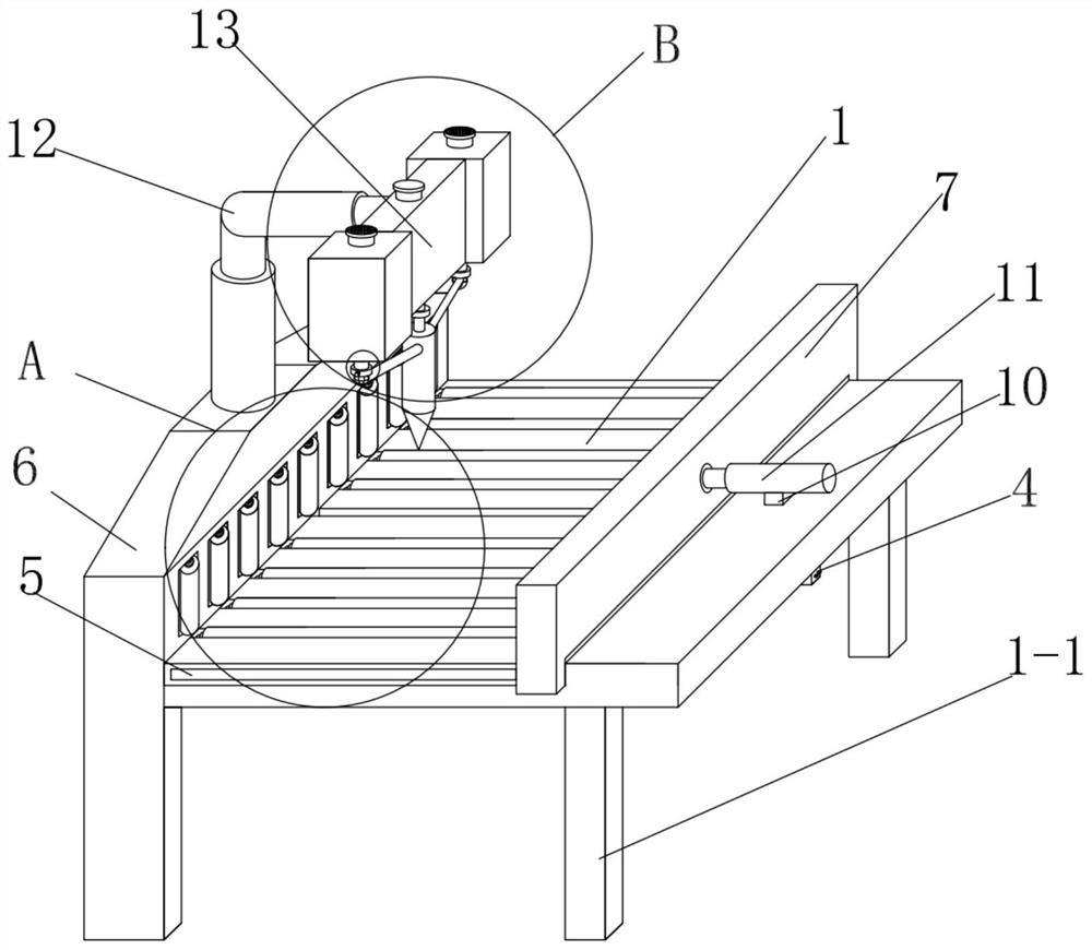
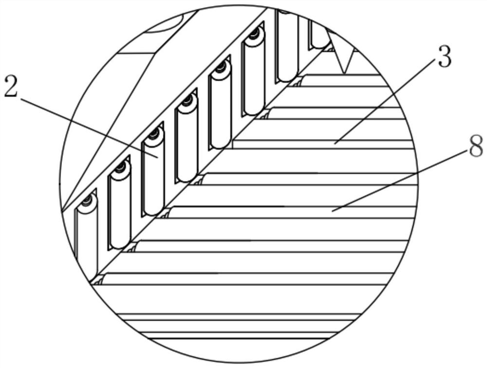
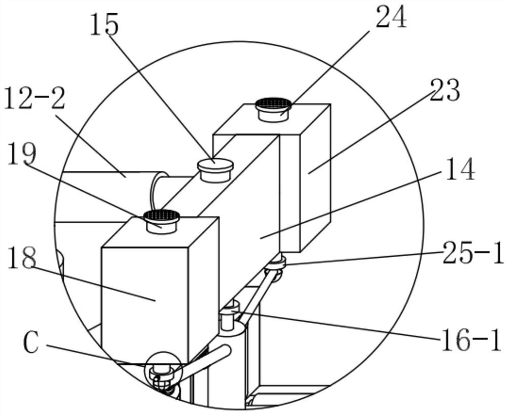
[0029]An energy-saving gluing machine for stone processing, including a workbench 1, a clamping mechanism I6, a clamping mechanism II7, a moving device 12, and a gluing mechanism 13. Leg 1-1, the workbench 1 is half-embedded with a set of auxiliary round rollers I2, the inside of the workbench 1 is provided with a fixed seat I2-1, the auxiliary round roller I2 and the fixed seat I2-1 The space is movably connected by a group of bearings I2-2, the center of the workbench 1 is provided with a glue-coated seam 3, and a collection tank 4 is provided below the glue-coated seam 3, and a drawer is arranged in the collection chamber 4 Slot 4-1, chute 5 is provided on both sides of the workbench 1, and the upper part of the workbench 1 is respectively provided with a clamping mechanism I6 and a clamping mechanism II7, and the clamping mechanism I6 and clamping mechanism II7 A group of auxiliary round rollers II8 are semi-embedded respective...

Embodiment 2

[0033] Such as Figure 1-Figure 11 Shown:

[0034] An energy-saving gluing machine for stone processing, including a workbench 1, a clamping mechanism I6, a clamping mechanism II7, a moving device 12, and a gluing mechanism 13. Leg 1-1, the workbench 1 is half-embedded with a set of auxiliary round rollers I2, the inside of the workbench 1 is provided with a fixed seat I2-1, the auxiliary round roller I2 and the fixed seat I2-1 The space is movably connected by a group of bearings I2-2, the center of the workbench 1 is provided with a glue-coated seam 3, and a collection tank 4 is provided below the glue-coated seam 3, and a drawer is arranged in the collection chamber 4 Slot 4-1, chute 5 is provided on both sides of the workbench 1, and the upper part of the workbench 1 is respectively provided with a clamping mechanism I6 and a clamping mechanism II7, and the clamping mechanism I6 and clamping mechanism II7 A group of auxiliary round rollers II8 are semi-embedded respectiv...


PUM


Abstract

The invention discloses an energy-saving glue coating machine for stone machining, and belongs to the technical field of stone machining. The energy-saving glue coating machine comprises a workbench, a clamping mechanism, a moving device and a glue coating mechanism, wherein an auxiliary round roller I is embedded into the table surface of the workbench, a glue coating seam is reserved, a collecting groove is formed in the bottom of the glue coating seam, sliding grooves are formed in the side edges of the workbench respectively, the clamping mechanism I and the clamping mechanism II are arranged on the upper portion of the workbench respectively, a group of auxiliary round rollers II are arranged in the clamping mechanism I and the clamping mechanism II respectively, the clamping mechanism I is fixedly installed, pulleys are arranged at the joints of the clamping mechanism II and the workbench, and are in sliding connection with the sliding grooves, a servo electric push rod is further arranged on the upper portion of the workbench, the servo electric push rod pushes the clamping mechanism II to move horizontally, the moving device is arranged above the clamping mechanism I, and the horizontal side of the moving device is fixedly connected with the glue coating mechanism. According to the energy-saving glue coating machine, the technical problems that an existing device is tedious in glue coating process, high in glue coating cost and incapable of coating glue in real time are solved, and the energy-saving glue coating machine is mainly applied to the aspect of marble plate manufacturing.

Description

technical field [0001] The invention belongs to the technical field of stone processing, and in particular relates to an energy-saving gluing machine for stone processing. Background technique [0002] Patent application number: 202010522612.2, which discloses a gluing device for stone processing. In this invention, a vertical plate, a straight groove, a first arc-shaped groove, and a second arc-shaped groove are set, and the length of the straight groove is set as the glue-coating length. The component drives the moving column to slide on the inner wall of the second arc-shaped groove, straight groove and first arc-shaped groove in sequence, and correspondingly moves the gluing head down to approach the stone, and the bottom of the gluing head touches the stone for gluing, and the gluing is completed After moving up and away from the stone, it is not convenient for side gluing. The existing stone gluing device cannot meet the side gluing or the effect of side gluing is not ...

Claims


Application Information

Patent Timeline
IPC IPC(8): B05C5/02B05C11/00B05C11/10B05C13/02
CPCB05C5/0208B05C13/02B05C11/1036B05C11/00
Inventor 赵淑婷王晶晶
Owner 连云港奥林匹亚石材有限公司
Learn More