
LED light source cutting method

A technology of LED light source and cutting method, which is applied in metal processing and other directions, can solve problems such as low work efficiency, and achieve the effect of improving work efficiency and quality

Active Publication Date: 2021-08-24
SHENZHEN CRESCENT OPTOELECTRONICS
View PDF7 Cites 1 Cited by
  • Summary
  • Abstract
  • Description
  • Claims
  • Application Information

AI Technical Summary

Problems solved by technology

[0004] The purpose of the present invention is to provide a LED light source cutting method, which aims to solve the problem of low work efficiency due to manual cutting of LED light source boards in the prior art

Method used


Image

  • LED light source cutting method
  • LED light source cutting method
  • LED light source cutting method

Examples


Embodiment Construction

[0026] In order to make the object, technical solution and advantages of the present invention clearer, the present invention will be further described in detail below in conjunction with the accompanying drawings and embodiments. It should be understood that the specific embodiments described here are only used to explain the present invention, not to limit the present invention.

[0027] In the drawings of this embodiment, the same or similar symbols correspond to the same or similar components; The indicated orientation or positional relationship is based on the orientation or positional relationship shown in the drawings, and is only for the convenience of describing the present invention and simplifying the description, rather than indicating or implying that the referred device or element must have a specific orientation, or in a specific orientation. Construction and operation, so the words describing the positional relationship in the drawings are only for illustrative...


PUM


Abstract

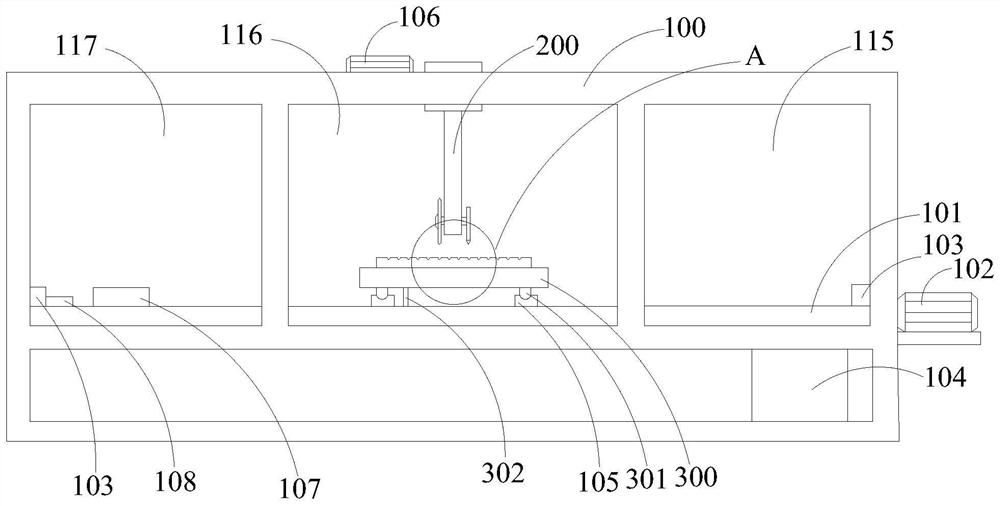
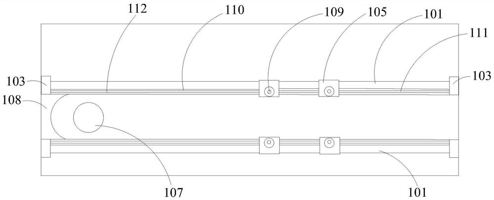
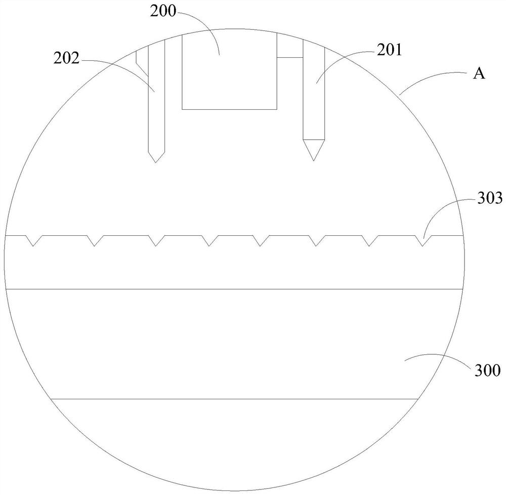
The invention relates to the technical field of LEDs, and discloses an LED light source cutting method. The LED light source cutting method comprises the following steps that an LED light source plate is placed on a cutting table, and the LED light source plate is adsorbed to the cutting table through vacuum suction holes, wherein the LED light source plate comprises a plurality of LED light source units which are arranged in a matrix mode, the LED light source plate is provided with a plurality of transverse connecting lines and longitudinal connecting lines which separate the adjacent LED light source units, the side edges of the adjacent LED light source units are connected through the transverse connecting lines or the longitudinal connecting lines, a cutting knife and a polishing grinding wheel which moves synchronously in the same direction with the cutting knife are arranged above the cutting table, the cutting knife and the polishing grinding wheel are arranged at intervals in the transverse direction, and the interval between the cutting knife and the polishing grinding wheel is equal to the transverse width of one or more LED light source units; and driving the cutting knife to cut the LED light source plate along the longitudinal connecting lines, and separating the LED light source units on the two sides of each longitudinal connecting line; the polishing grinding wheel synchronously moves along with the cutting knife in the same direction to polish the side edges of the LED light source units.

Description

technical field [0001] The invention relates to the technical field of LEDs, in particular to a method for cutting LED light sources. Background technique [0002] With the rapid development of LED technology and the gradual improvement of LED light efficiency, the application of LED will become more and more extensive. As the global energy shortage becomes more and more serious, people pay more and more attention to the development prospect of LED in the lighting market. LED will be a potential light source to replace incandescent lamps, tungsten lamps and fluorescent lamps. [0003] In the field of LED lamp production and assembly, there is a process to divide the LED light source board, that is, the process of LED light source board production is a large-area full-page SMT, and the entire LED light source board needs to be divided into small units of LED light source units. , the traditional way is to manually divide along the reserved dividing line, which is simple and ...

Claims


Application Information

Patent Timeline
Patent Type & Authority Applications(China)
IPC IPC(8): B26D1/18B26D7/20B26D7/01B24B1/00
CPCB26D1/18B26D7/20B26D7/018B24B1/00
Inventor 邹义明杜琤饶志平操彬
Owner SHENZHEN CRESCENT OPTOELECTRONICS
Learn More