Mold device for plastic molding, injection molding machine and demolding method

A technology of plastic molding and injection molding machine, which is applied in the field of plastic molding mold devices, injection molding machines, and demoulding. It can solve problems such as surface scratches, damage to the shape of injection molded parts, and damage to the structure of tableware, so as to improve production efficiency and improve demoulding. Efficiency and Difficulty Reduction Effects

Active Publication Date: 2021-08-24
宁波昌亚新材料科技股份有限公司
View PDF3 Cites 0 Cited by
  • Summary
  • Abstract
  • Description
  • Claims
  • Application Information

AI Technical Summary

Problems solved by technology

[0003] However, since the shells of molded injection molded parts are relatively thin, such as tableware and other structures, if the force of the push rod assembly is too large, the structure of the tableware will be destroyed. More specifically, although the injection molded parts have been overcooled, in fact, The injection molded part adhered to the mold still has a relatively high temperature, which means that its structure is not yet in a fully formed state, so under the action of the push rod assembly, the shape of the injection molded part will still be destroyed, for example, it is very easy to Its surface causes scratches, affecting the overall aesthetics of injection molded parts

Method used


Image

  • Mold device for plastic molding, injection molding machine and demolding method
  • Mold device for plastic molding, injection molding machine and demolding method
  • Mold device for plastic molding, injection molding machine and demolding method

Examples


Embodiment 1

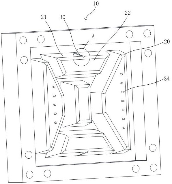
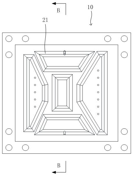
[0042] see Figure 1-Figure 5 , which is a schematic structural view of a mold device 100 for plastic molding provided in Embodiment 1 of the present invention. The mold device 100 includes, for example, a first mold 10 , a second mold and a stripping assembly 30 . Specifically, the first mold 10 is provided with a core 20; the second mold cooperates with the first mold 10 to form an injection molding space, and the injection molding space is used for injection molding of injection molded parts.

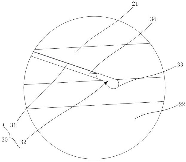
[0043] Further, the demoulding assembly 30 is disposed on the outer surface 22 of the core 20 , and the demoulding assembly 30 includes at least one chute 32 and at least one movable rod 31 , for example. At least one chute 32 is provided in the core 20, and a first opening 33 is formed on the outer surface 22 of the core 20; at least one movable rod 31 is telescopically arranged in the corresponding chute 32, wherein the movable rod 31 includes The abutting end 34 is used for abut...

Embodiment 2

[0046] combine Figure 1-5 The difference between the second embodiment and the first embodiment above is that the mold device 100 in the second embodiment is provided with an air blowing assembly, specifically, the air blowing assembly is arranged on the outer surface 22 of the core 20, and the The blowing component is provided with a plurality of blowing ports.

[0047] In a specific embodiment, the efficiency of demoulding is improved by synergizing the blowing component and the demoulding component 30 . Specifically, in the prior art, in the technical solution for demoulding, the use of the blowing component for demoulding has occurred, but there are many problems in using the blowing component alone to achieve the demoulding effect, For example, it is difficult to adjust the blowing force of the blowing assembly according to the degree of cooperation between each injection molded part and the mold device 100. The injection molded parts are directly blown off from the co...

Embodiment 3

[0063] see Figure 6 , which is a schematic structural diagram of an injection molding machine 200 for plastic processing provided by Embodiment 3 of the present invention. The injection molding machine 200 includes, for example, the mold device 100 as described in the first embodiment above, and / or includes the content as described in the second embodiment above.


PUM


Abstract

The invention provides a mold device for plastic molding, an injection molding machine and a demolding method, and the mold device comprises a first mold, a second mold and a demolding assembly, and a mold core is arranged in the first mold. The second mold is matched with the first mold to form an injection molding space, and the injection molding space is used for injection molding of an injection molding part. The demolding assembly is arranged on the outer surface of the mold core and comprises at least one sliding groove and at least one movable rod, the sliding groove is formed in the mold core, and a first opening is formed in the outer surface of the mold core. The movable rod is telescopically arranged in the sliding groove. The movable rod comprises an abutting end, and the abutting end is used for abutting against the injection molding part. When the movable rod completely enters the sliding groove, the maximum distance between the abutting end and the corresponding first opening is d, and d is larger than 0. The problems that in the demolding process of the injection molding part, the structure of the injection molding part is liable to be damaged by a push rod assembly, and the production efficiency is reduced are solved.

Description

technical field [0001] The invention relates to the technical field of plastic molding, in particular to a mold device for plastic molding, an injection molding machine and a demoulding method. Background technique [0002] Injection molded parts can be used in a wide range of fields. For example, they can be used in the catering industry, especially in injection molding to form structures such as lunch boxes. Specifically, plastic products are processed by mixing and stirring plastic raw materials, and then hot-melted and then poured into the mold through the injection port, and after being cooled by the cooling liquid, the injection molded parts are formed in the mold. Due to the physical characteristics of thermal expansion and cold contraction, the injection molded part adheres to the core of the mold. Therefore, in the prior art, the push rod assembly is often used to act on the injection molded part to complete demoulding. [0003] However, since the shells of molded ...

Claims


Application Information

Patent Timeline
Patent Type & Authority Applications(China)
IPC IPC(8): B29C45/33B29C45/43B29C45/42
CPCB29C45/332B29C45/4225B29C45/43
Inventor 徐建海王美兰
Owner 宁波昌亚新材料科技股份有限公司
Why Eureka
Try Eureka