Brake safety protection system for new energy automobile

A new energy vehicle, safety protection technology, applied in the field of new energy vehicle brake safety protection system, can solve the problems of increasing vehicle maintenance costs, vehicle spontaneous combustion incidents, etc., to achieve the effect of preventing vehicle spontaneous combustion incidents, reducing car accidents, and ensuring safety

Active Publication Date: 2021-08-24
SHENZHEN CHENGYIXIN TECH
View PDF4 Cites 2 Cited by
  • Summary
  • Abstract
  • Description
  • Claims
  • Application Information

AI Technical Summary

Problems solved by technology

[0003] However, in the traditional new energy vehicle braking safety protection system, because the vehicle does not protect the internal structure of the braking device in the case of emergency braking, some parts of the vehicle are damaged and the maintenance cost of the vehicle is increased. What is more serious is Sometimes the vehicle will spontaneously ignite due to the high temperature of the braking system during the braking process. For this reason, a new energy vehicle braking safety protection system is proposed to solve the above problems

Method used


Image

  • Brake safety protection system for new energy automobile
  • Brake safety protection system for new energy automobile
  • Brake safety protection system for new energy automobile

Examples


Embodiment 1

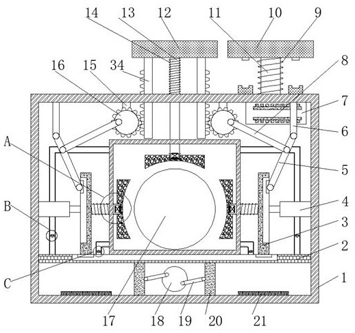
[0027] see Figure 1-5 As shown, a new energy vehicle braking safety protection system proposed by the present invention includes a first box body 1, a brake plate 33, and a wheel shaft 17. The inner walls of both sides of the first box body 1 are welded with partitions 2, and the partitions The top of 2 is fixedly connected with the second box body 23 by bolts, the top of the first box body 1 is sleeved with the second extruding column 13 that penetrates and extends into the second box body 23, the second extruding column 13 and the second extruding column 13 The insides of the three extruding columns 27 are provided with a first chamber 29, the top of the second extruding column 13 is welded with the brake pedal 12, the back of the first box body 1 is fixedly connected with a driving motor 22 by bolts, and the output of the driving motor 22 The end is welded with a turntable 18 located in the first box body 1. Two third connecting rods 19 are hinged on the front of the turnt...

Embodiment 2

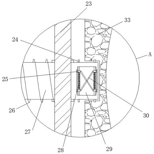
[0029] see Figure 1-5 As shown, on the basis of Embodiment 1, two movable plates 3 are slidably connected to the top of the partition plate 2, and the sides of the movable plates 3 close to each other are welded with a third extruded part that penetrates and extends into the second box body 23. Column 27, the both sides of second box body 23 are welded with the 3rd spring 26 that is sleeved on the outer ring of 3rd extruding column 27, the other end of 3rd spring 26 is welded with the side that movable plate 3 is close to each other, the first The inner walls of both sides of the chamber 29 are slidably connected with two movable blocks 25, the side of the movable blocks 25 close to each other is welded with a fourth spring 28, and the ends of the movable blocks 25 close to each other are hinged with a fourth connecting rod 30, two fourth The middle parts of the connecting rods 30 are hinged to each other, and the side of the movable block 25 away from each other is welded wi...

Embodiment 3

[0031]see Figure 1-5 As shown, on the basis of Embodiment 1, the bottom of the brake pedal 12 is welded with a second spring 14 sleeved on the outer ring of the second extrusion column 13, and the end of the second spring 14 away from the brake pedal 12 is connected to the first box body. 1, the bottom of the brake pedal 12 is welded with two first racks 34 penetrating and extending into the first box 1, and the top of the first box 1 is welded with two supporting columns 15, the supporting columns 15 The front is rotatably connected with a first gear 16, the front of the first gear 16 is hinged with a second connecting rod 8, and the end of the second connecting rod 8 away from the first gear 16 is hinged with a first connecting rod 5, and the top of the first box body 1 Two support rods 6 are welded on the inner wall, and the end of the support rod 6 away from the top inner wall of the first box body 1 is hinged to the first connecting rod 5 , and the end of the first conne...


PUM


Abstract

The invention discloses a brake safety protection system for a new energy automobile, relates to the technical field of new energy automobiles, and aims to solve the problems that the internal structure of a brake device is not protected under the emergency brake condition of the automobile, and the like. The brake safety protection system comprises a first box body, a brake plate and a wheel axle, partition plates are welded to the inner walls of the two sides of the first box body, and the top of each partition plate is fixedly connected with a second box body through bolts. The braking purpose can be achieved through the brake plate, the internal structure of the second box body can be emergently cooled when an automobile is emergently braked, the brake plate can be conveniently disassembled and assembled, an operator can conveniently replace the brake plate by himself, the safety of the operator is guaranteed to a certain degree, car accidents are reduced, damage to some parts of the vehicle in the emergency braking process is avoided, and spontaneous combustion of the vehicle due to the fact that the temperature is too high after emergency braking can be prevented.

Description

technical field [0001] The invention relates to the technical field of new energy vehicles, in particular to a braking safety protection system for new energy vehicles. Background technique [0002] New energy vehicles refer to the use of unconventional vehicle fuels as power sources (or the use of conventional vehicle fuels and new vehicle power devices), and the comprehensive vehicle power control and advanced technology in driving, the formation of advanced technical principles, with Vehicles with new technology and new structure, new energy vehicles include four types of hybrid electric vehicles (HEV), pure electric vehicles (BEV, including solar vehicles), fuel cell electric vehicles (FCEV), other new energy sources (such as supercapacitors, high-efficiency energy storage such as flywheels) automobiles, etc. [0003] However, in the traditional new energy vehicle braking safety protection system, because the vehicle does not protect the internal structure of the brakin...

Claims


Application Information

Patent Timeline
Patent Type & Authority Applications(China)
IPC IPC(8): B60T5/00B60T1/06
CPCB60T1/062B60T5/00
Inventor 邱蓉华
Owner SHENZHEN CHENGYIXIN TECH
Why Eureka
Try Eureka