Novel reverse navigation structure device of water navigation body

A new type of reverse sailing technology, applied in the direction of pump device, hull, hull design, etc., can solve problems such as blockage of water inlet, occupying a considerable ship's storage capacity, and increase of ship's navigation resistance

Pending Publication Date: 2021-08-24
曾德润
View PDF1 Cites 5 Cited by
  • Summary
  • Abstract
  • Description
  • Claims
  • Application Information

AI Technical Summary

Problems solved by technology

[0050] 1. The propeller power transmission system and structure are generally more complicated, and the propeller power transmission system and structure of large ships, especially large surface ships such as aircraft carriers, can be described as very complicated, which needs to occupy a considerable ship's storage capacity, resulting in a waste of effective storage capacity of the ship;
[0051] 2. The manufacture of large, especially super-large propellers requires the consumption of a large amount of special materials and the support of special processing equipment, which significantly increases the difficulty and cost of manufacturing, and is not easy to assemble, disassemble and maintain;
[0052] 3. Large, especially super-large propellers are heavy, and the self-weight of a single super-large propeller can even reach hundreds of tons, which increases the ship's own weight and increases the ship's navigation resistance;
[0053] 4. Large, especially super-large propellers are prone to cavitation during operation, causing damage to the propeller blade body, resulting in reduced propulsion efficiency and unnecessary noise;
[0054] 5. For large, especially super-large propellers, when the ship is under no-load or light-load navigation, the blades will grow out of the water surface, resulting in periodic uneven force on the propeller blades during rotation;
[0055] 6. Propellers, especially large and super-large propellers, are likely to cause mechanical damage to aquatic organisms;
[0056] 7. The propeller propulsion is at high risk of being entangled
[0058] 1. The pump spray propulsion implements bottom water intake, and its water intake efficiency is not as high as that of the upstream water intake;
[0059] 2. Pump jet propulsion implements bottom-to-bottom water intake. When navigating in waters with a lot of aquatic plants or debris, the water inlet is easily blocked and affects water intake, resulting in reduced propulsion efficiency or even failure;
[0060] 3. Pump jet propulsion implements bottom-to-bottom water intake, and shallow water navigation is easy to inhale gravel and gravel in the water area, causing mechanical damage to the propulsion device;
[0061] 4. The deployment and installation of the pump-jet propulsion device needs to occupy a certain storage capacity at the stern of the ship
[0072] 1. The steering torque of the stern rudder is small, and it is difficult to support the ship to change direction quickly, and it is inconvenient for the ship to avoid emergency
[0073] The stern rudder of a ship is generally set as a single rudder and is deployed and installed on the centerline of the stern of the ship. The direction-changing force obtained by the deflection of the rudder blades is very short relative to the moment arm length of the ship's center axis, and the resulting direction-changing moment is small; that is, the double rudder method is adopted. Deployment, the two rudders are deployed and installed away from the center line of the stern of the ship, the direction-changing force obtained by the deflection of the two rudder rudder blades increases relative to the length of the moment arm of the ship's central axis, and the resulting direction-changing moment increases accordingly, but the increase is still limited , the rudder effect is still not obvious
[0074] 2. The bow direction change response of the ship's stern rudder change method is slow, which is inconvenient for the emergency avoidance of the ship
However, for ships without a bulbous bow, the direction-changing reaction speed of this ship will be greatly reduced; There will be formation of vortex, turbulent flow and turbulent flow at the structure, which will increase the resistance of the ship's navigation; the process of changing direction will increase additional energy consumption
Therefore, it still cannot be regarded as an ideal ship steering technology
[0077] 2. Rapid deceleration / braking of ships
The speed reduction / braking of sailing ships cannot be realized. In the general high-speed environment, especially in the case of high-density and high-speed sailing ships, there is a great risk of collision safety, which is obviously not suitable for the era of high speed
[0079] 3. The surge threat of high-speed and large-scale ships
[0080] When a high-speed and large-volume ship travels in a narrow waterway, typically an inland waterway, the huge volume of water discharged by the passing high-speed and large-volume ship is too late to be reduced, and it is forced to transport to both sides of the ship at high speed, resulting in a huge surge. The surge will have a strong impact on adjacent ships, embankments, and embankment facilities, and may cause tsunami-like damage
[0081] 4. The limit breakthrough problem of ships obtaining super propulsion
The advent of the era of universally high speeds will also affect revolutionary changes in marine military technology. For example, if the instantaneous speed of an aircraft carrier can reach or even exceed 100 knots, it may lead to major changes in the way carrier-based aircraft take off, and further lead to an increase in the structure of the aircraft carrier. change

Method used


Image

  • Novel reverse navigation structure device of water navigation body
  • Novel reverse navigation structure device of water navigation body
  • Novel reverse navigation structure device of water navigation body

Examples


Embodiment Construction

[0247] In order to make the purpose, technical solutions and advantages of the embodiments of the present invention clearer, the technical solutions in the embodiments of the present invention will be clearly and completely described below in conjunction with the drawings in the embodiments of the present invention. Obviously, the described embodiments It is a part of embodiments of the present invention, but not all embodiments. Based on the embodiments of the present invention, all other embodiments obtained by persons of ordinary skill in the art without creative efforts fall within the protection scope of the present invention.

[0248] [Explanation of terms]:

[0249] Facing water intake: the water inlet deployed by the axial jet propulsion device is facing the direction of the ship.

[0250] Centrifugal axial flow injection thrust device: The fluid enters in a centrifugal manner and outputs an injection thrust device in an axial flow manner.

[0251] Dual working mediu...


PUM


Abstract

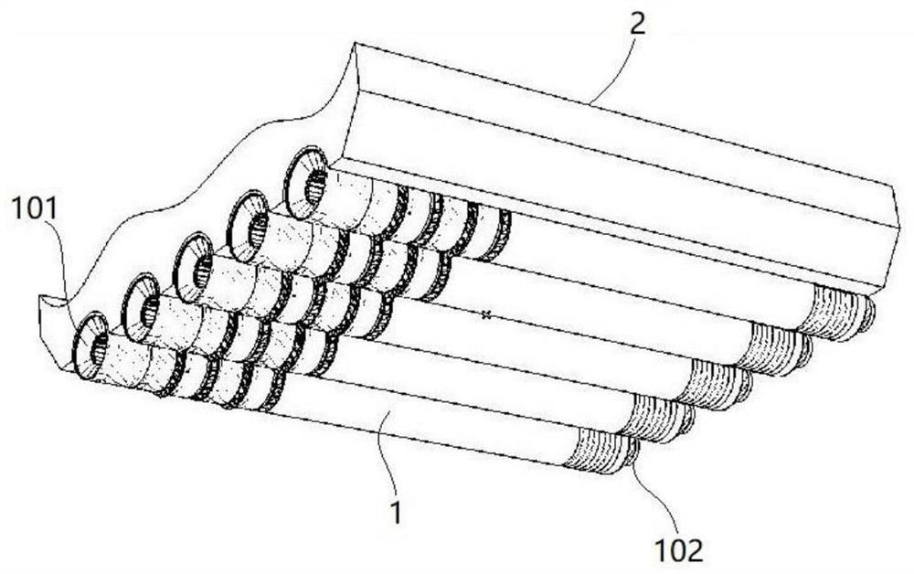
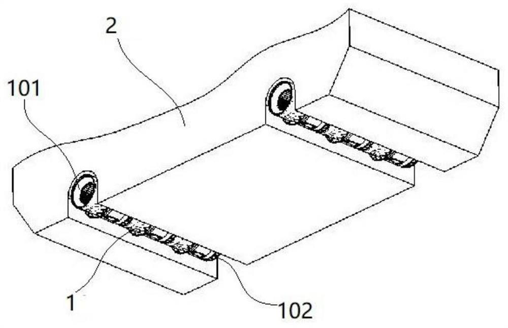
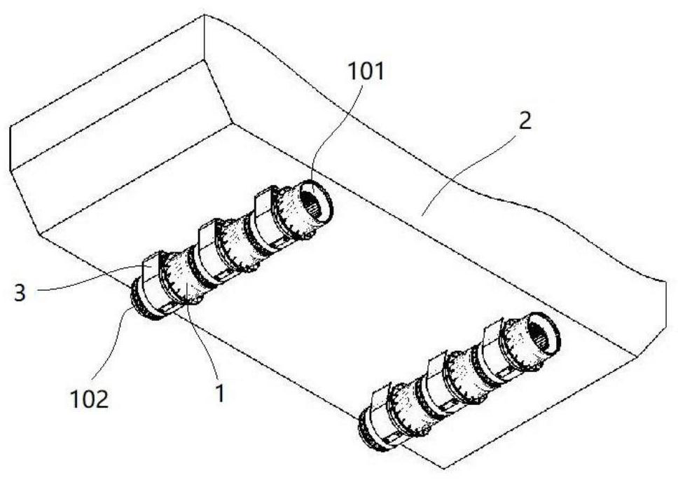
The invention provides a novel backing structure device of a water navigation body, the main body structure of the backing structure device is a storable backing water bucket, the backing water bucket is deployed and mounted on a bottom plate behind a water injection nozzle of a spraying and pushing device deployed and mounted on the outer side of a bottom plate of the water navigation body, and the width of the backing water bucket is greater than the total width of the water injection nozzles of all corresponding spraying and pushing devices in front. According to the water navigation body reverse navigation operation, when only the spraying and pushing device corresponding to the reverse navigation water bucket works in the water spraying state, the reverse navigation water bucket is moved out of the storage bin according to the control instruction, water flow sprayed out of the water spraying opening of the spraying and pushing device is blocked so that the water flow can flow back, reverse navigation force is obtained and transmitted to the water navigation body, and reverse navigation of the water navigation body is achieved. When the propelling work of the water navigation body propelling device is stopped, the backward navigation water bucket of the water navigation body in the running state is released, the backward navigation water bucket obtains the resistance for preventing the water navigation body from continuing to navigate, a certain braking effect can be achieved, strong speed reduction and braking resultant force can be formed through combined operation with other speed reduction/braking devices, and rapid speed reduction/braking of the ship is achieved.

Description

technical field [0001] The invention relates to ship propulsion technology, in particular to a new type of reversing structural device for a water craft. Background technique [0002] The high energy efficiency of ships at high speeds is an eternal goal pursued by ship technology research. [0003] The reality is that even in today's technologically advanced society, the generally low speed and energy efficiency of ships is still an objective worldwide problem, and no ideal solution has been found so far. [0004] The analysis of ship navigation resistance and propulsion technology can enhance our understanding of the limitations and deficiencies of current propulsion technology, and help open a useful idea to solve the problem of generally low ship speed and energy efficiency. [0005] Qualitative analysis of the main resistance of the ship's navigation: the ship's navigation has at least the following navigation resistance—— [0006] When the ship is sailing, the water b...

Claims


Application Information

Patent Timeline
Patent Type & Authority Applications(China)
IPC IPC(8): B63H11/02B63H11/12B63B1/38B63B1/40
CPCB63B1/38B63B1/40B63B2001/387B63H11/02B63H11/12B63H2011/004B63H2011/008B63B1/30B63H11/00B63H11/04B63H11/08B63H25/44F04D25/08Y02T70/10Y02T70/50
Inventor 曾德邻曾固
Owner 曾德润
Why Eureka
Try Eureka