Flexible belt assembly line

An assembly line and belt technology, applied in the direction of cleaning devices, transportation and packaging, conveyor objects, etc., to achieve the effect of preventing falling off

Pending Publication Date: 2021-08-24
莆田市嘉汇顺贸易有限公司
View PDF7 Cites 1 Cited by
  • Summary
  • Abstract
  • Description
  • Claims
  • Application Information

AI Technical Summary

Problems solved by technology

[0003] In order to reduce the wear of the contact surface between the pulley and the belt, the flexible belt assembly line usually uses a split pulley to drive the belt. However, there is a gap between the support roller and the support roller of the pulley pulley. When the belt assembly line conveys some materials, the conveyed materials Snaps easily in the gap between the support rollers of split drums

Method used


Image

  • Flexible belt assembly line
  • Flexible belt assembly line
  • Flexible belt assembly line

Examples


Embodiment 1

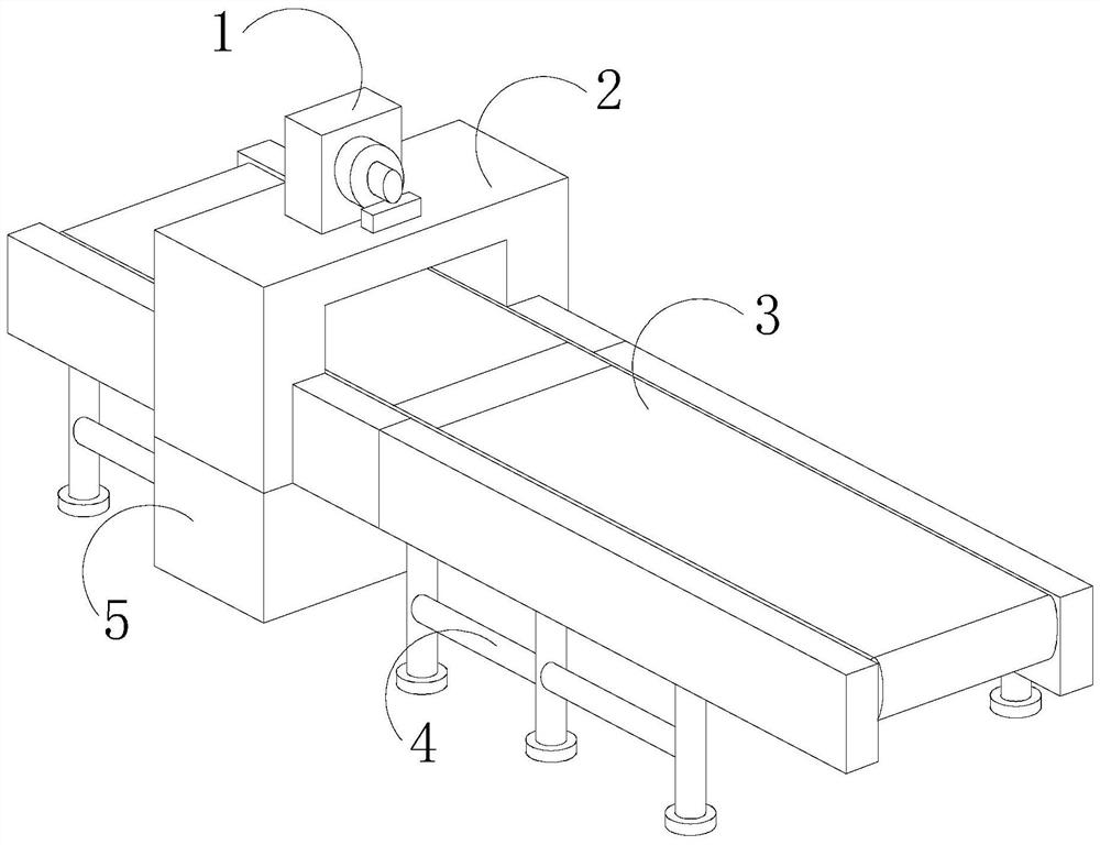
[0027] see Figure 1-Figure 5 , a flexible belt assembly line, its structure includes a motor 1, a work box 2, a conveyor 3, a support 4, a base 5, the work box 2 is provided with a motor 1, the motor 1 is movably connected with the work box 2, and the The bottom of the work box 2 is provided with a base 5, the base 5 is flexibly connected with the work box 2, the bottom of the transmitter 3 is equipped with a support 4, and the support 4 is connected with the transmitter 3;

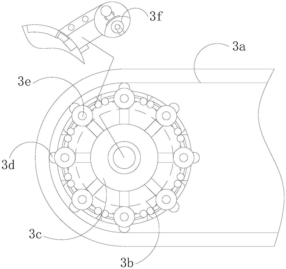
[0028] The conveyor 3 is provided with a belt 3a, an operator 3b, a rotating roller 3c, a contact block 3d, a supporting roller 3e, and a knocking block 3f, the supporting roller 3e is movably connected with the rotating roller 3c, and the contacting block 3d is mounted on On the support roller 3e, the contact block 3d is in clearance fit with the belt 3a, the operator 3b is installed on the rotating roller 3c, the knocking block 3f is arranged on the support roller 3e, and the knocking block 3f and the ...

Embodiment 2

[0036] see Figure 1-Figure 6 , a flexible belt assembly line, its structure includes a motor 1, a work box 2, a conveyor 3, a support 4, a base 5, the work box 2 is provided with a motor 1, the motor 1 is movably connected with the work box 2, and the The bottom of the work box 2 is provided with a base 5, the base 5 is flexibly connected with the work box 2, the bottom of the transmitter 3 is equipped with a support 4, and the support 4 is connected with the transmitter 3;

[0037] The conveyor 3 is provided with a belt 3a, an operator 3b, a rotating roller 3c, a contact block 3d, a supporting roller 3e, and a knocking block 3f, the supporting roller 3e is movably connected with the rotating roller 3c, and the contacting block 3d is mounted on On the support roller 3e, the contact block 3d is in clearance fit with the belt 3a, the operator 3b is installed on the rotating roller 3c, the knocking block 3f is arranged on the support roller 3e, and the knocking block 3f and the ...


PUM


Abstract

The invention discloses a flexible belt assembly line. The flexible belt assembly line structurally comprises a motor, a working box, a conveyor, a support and a base, wherein the motor is arranged on the working box and movably connected to the working box, the base is arranged at the bottom of the working box and movably connected to the working box, the support is installed at the bottom of the conveyor and connected to the conveyor, the conveyor is provided with a belt, an operator, a rotating roller, contact blocks and supporting rollers, wherein the supporting rollers are arranged on the outer edge of the rotating roller, the supporting rollers are movably connected to the rotating roller, and the contact blocks are installed on the supporting rollers. According to the flexible belt assembly line, when the rotating roller rotates, sliding shafts of knocking blocks slide along a sliding cavity and knock a sealing layer constantly, the clamping contact faces of clamping materials clamped by the supporting rollers and the supporting rollers to generate vibration, the materials are shaken off through the shaking force of beating, and the materials cannot be easily clamped in gaps of the supporting rollers.

Description

technical field [0001] The invention relates to the field of belt assembly lines, in particular to a flexible belt assembly line. Background technique [0002] The flexible belt assembly line has the advantages of large conveying capacity, simple structure, convenient maintenance, and standardized components. According to the requirements of the conveying process, it can be conveyed by a single unit, or can be composed of multiple units or combined with other conveying equipment to form a horizontal or inclined conveying system to meet different needs. Layout type of operation line needs; [0003] In order to reduce the wear of the contact surface between the pulley and the belt, the flexible belt assembly line usually uses a split pulley to drive the belt. However, there is a gap between the support roller and the support roller of the pulley pulley. When the belt assembly line conveys some materials, the conveyed materials Snaps easily in the gap between the support rolle...

Claims


Application Information

Patent Timeline
IPC IPC(8): B65G45/10
CPCB65G45/105
Inventor 蔡玉蓉
Owner 莆田市嘉汇顺贸易有限公司
Why Eureka
Try Eureka