flare detection method

A detection method and technology in the core area, applied in the field of flare detection, can solve problems such as poor flare detection effect and low detection efficiency, and achieve the effect of improving inspection efficiency and consistency

Active Publication Date: 2022-08-02
威海世高光电子有限公司
View PDF15 Cites 0 Cited by
  • Summary
  • Abstract
  • Description
  • Claims
  • Application Information

AI Technical Summary

Problems solved by technology

[0004] The purpose of the present invention is to provide a flare detection method to solve the problems of poor flare detection effect and low detection efficiency in the prior art

Method used


Image

  • flare detection method
  • flare detection method
  • flare detection method

Examples


Embodiment Construction

[0040] The present invention will be described in detail below with reference to the various embodiments shown in the accompanying drawings. However, these embodiments do not limit the present invention, and structural, method, or functional transformations made by those skilled in the art based on these embodiments are all included in the protection scope of the present invention.

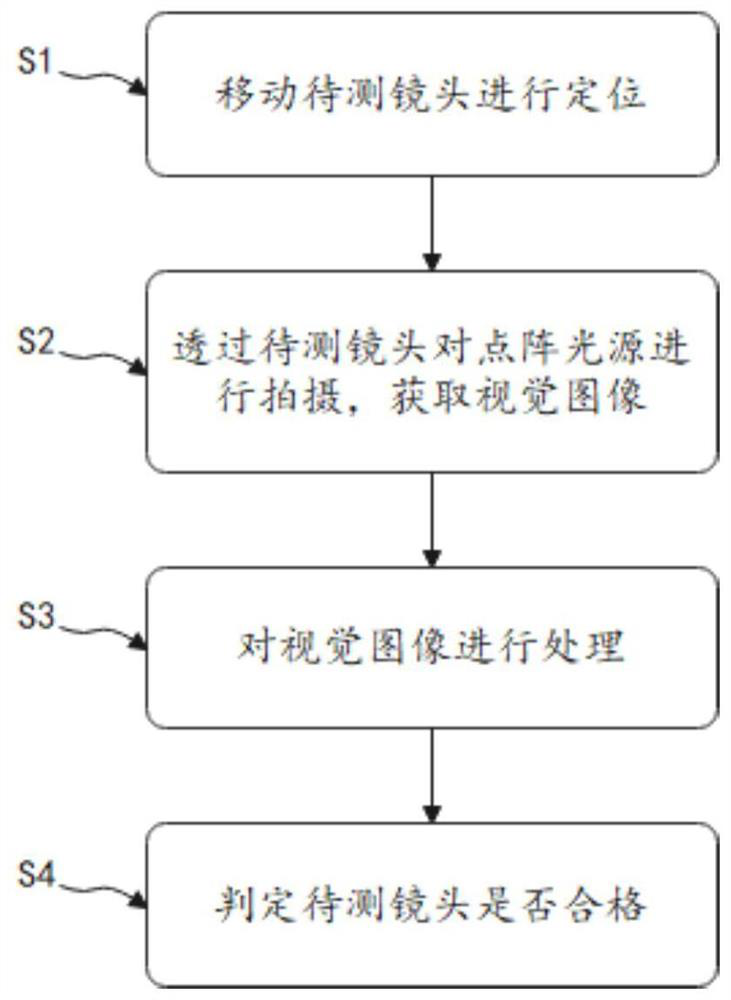
[0041] The invention discloses a flare detection method, comprising:

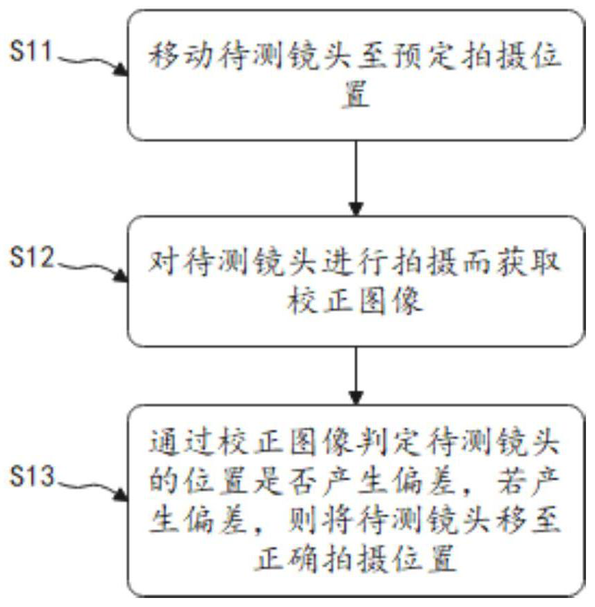
[0042] S1: Move the lens to be tested for positioning;

[0043] S2: Shoot the dot matrix light source through the lens to be tested to obtain a visual image;

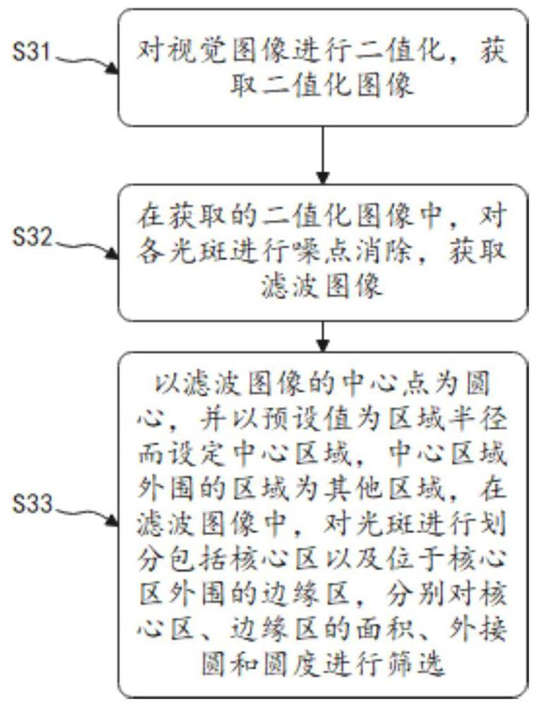
[0044] S3: Process the visual image;

[0045] S4: Determine whether the lens to be tested is qualified.

[0046] Each device in this embodiment will be described in detail below with reference to the accompanying drawings.

[0047] ginseng figure 1 As shown, a flare detection method in this embodiment includes:

[0048] S1: Move the lens to be tested for positionin...


PUM


Abstract

The invention discloses a flare detection method, comprising: S1, moving a lens to be tested for positioning; S2, photographing a dot matrix light source through the lens to be tested to obtain a visual image; S3, processing the visual image; S4, determining Whether the lens to be tested is qualified. The invention evaluates and judges the lens flare phenomenon, and automatically judges whether the lens flare phenomenon meets the standard by processing and comparing the light spot shape in the visual image, and displays the judgment result, thereby improving the inspection efficiency and consistency of the lens flare phenomenon.

Description

technical field [0001] The invention belongs to the technical field of automatic detection, in particular to a flare detection method. Background technique [0002] Lenses are required on many devices that need to be imaged. When shooting light sources or strong light objects through the lens, some halos, shadows or flares radiating outward will appear on the edge of the image. These are collectively called flares. The quality of the image is seriously affected, and the lens needs to be subjected to a flare test before it leaves the factory to screen qualified products. The existing flare detection effect is poor and the detection efficiency is low. [0003] Therefore, in view of the above technical problems, it is necessary to provide a flare detection method. SUMMARY OF THE INVENTION [0004] The purpose of the present invention is to provide a flare detection method to solve the problems of poor flare detection effect and low detection efficiency in the prior art. [...

Claims


Application Information

Patent Timeline
Patent Type & Authority Patents(China)
IPC IPC(8): G06T7/00G06T7/62G06T7/80G06T5/00
CPCG06T7/0002G06T7/80G06T7/62G06T5/002G06T2207/10004G06T2207/30244
Inventor 侯成龙金贤国郭晓婷赵敏
Owner 威海世高光电子有限公司
Why Eureka
Try Eureka