

Digital display device
A technology of digital display and display device, which is applied in identification devices, signal transmission systems, instruments, etc., can solve the problems of unstable output voltage and frequency, failure data cannot be read normally, and cannot work, etc. Scene rich effects
- Summary
- Abstract
- Description
- Claims
- Application Information
AI Technical Summary
Problems solved by technology
Method used
Image

Examples
Embodiment 1
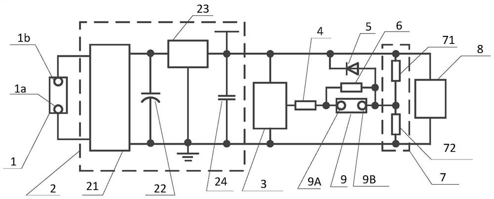
[0037] Such as figure 1 As shown, in this example, the two terminals of the power supply interface 1 (AC input interface) are terminal 1a and terminal 1b respectively. The power supply circuit 2 includes a step-down rectifier module 21 , a capacitor 22 , an LDO voltage stabilizing device 23 and a capacitor 24 . The power consumption circuit includes an MCU 3 , a step-down circuit 7 , and an equivalent low-voltage load 8 . The step-down circuit 7 includes a voltage dividing resistor 71 and a voltage dividing resistor 72 . The equivalent low-voltage load 8 includes modules or components such as a display and an infrared receiver.
[0038] The function expansion interface 9 has a two-terminal structure, including a terminal 9A and a terminal 9B. Terminal 9A is connected to ADC pin of microcontroller MCU 3 through resistor 4 . The terminal 9B is connected between the voltage dividing resistor 71 and the voltage dividing resistor 72 of the step-down circuit 7 , and is connected...
Embodiment 2
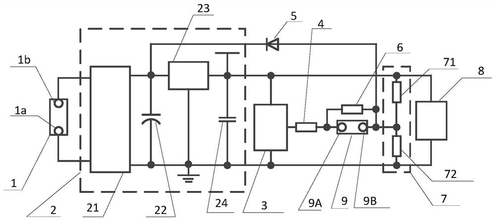
[0048] This embodiment is basically the same as Embodiment 1, the difference is: the terminal 9A of the two-pin function expansion interface 9 is connected to the ADC pin of the microcontroller MCU 3 through a resistor 4, and connected to the LDO voltage stabilizing device 23 through a diode Output terminal positive. The terminal 9B is connected between the voltage dividing resistor 71 and the voltage dividing resistor 72 of the step-down circuit 7, and a transformer sampling resistor 6 is connected in parallel between the terminal 9A and the terminal 9B.
[0049] When there is no AC input at both ends 1a and 1b of the power supply interface 1, connect the positive pole of the 5V DC power supply to the terminal 9A of the function expansion interface 9, and connect the negative pole of the 5V DC power supply to the terminal 1a of the power supply interface, so as to realize DC power supply to the display device .
Embodiment 3
[0051] This embodiment is basically the same as Embodiment 1, except that the terminal 9A of the two-pin function expansion interface 9 is connected to the ADC pin of the microcontroller MCU 3 through a resistor 4 . The terminal 9B is only connected to the negative output terminal of the power supply circuit 2 through the resistor 72 , and connected to the positive output terminal of the LDO voltage stabilizing device 23 through the diode 5 . A transformer sampling resistor 6 is connected in parallel between terminal 9A and terminal 9B.
[0052] When the two ends of the function expansion interface 9 are connected to the current transformer, the current transformer outputs an AC voltage signal proportional to the current detected by the transformer through the transformer sampling resistor 6, and the negative half cycle of the signal will be clamped by the protection diode in the MCU to supply power. The output terminal of the circuit 2 is negative, and the MCU 3 realizes the ...
PUM
 Abstract
Description
Claims
Application Information