Double concentrated winding permanent magnet synchronous motor

A permanent magnet synchronous motor and concentrated winding technology, which is applied to synchronous motors with stationary armatures and rotating magnets, magnetic circuits, electromechanical devices, etc., can solve the problem of large eddy current loss and large harmonic content of magnetomotive force in rotor permanent magnets , permanent magnet irreversible retreat and other issues, to achieve good low-speed stability, reduce harmonic content, and reduce torque fluctuations

Active Publication Date: 2022-07-01
HARBIN INST OF TECH
View PDF5 Cites 0 Cited by
  • Summary
  • Abstract
  • Description
  • Claims
  • Application Information

AI Technical Summary

Problems solved by technology

[0004] The purpose of the present invention is to solve the large harmonic content of the magnetomotive force of the traditional fractional slot concentrated winding. When the energization frequency of the motor winding is high and the overload multiple is large, the eddy current loss of the rotor permanent magnet is large, and the temperature of the permanent magnet rises, which is likely to cause permanent Irreversible demagnetization of magnets

Method used


Image

  • Double concentrated winding permanent magnet synchronous motor
  • Double concentrated winding permanent magnet synchronous motor
  • Double concentrated winding permanent magnet synchronous motor

Examples


specific Embodiment approach 1

[0076] Embodiment 1: The double concentrated winding permanent magnet synchronous motor described in this embodiment includes a coaxially nested stator and a rotor with an air gap between them. The permanent magnet synchronous motor has an outer rotor structure or an inner rotor structure. The rotor includes a rotor core and a plurality of permanent magnets. The plurality of permanent magnets are evenly fixed on the rotor core in an alternate arrangement of N and S poles. The rotor is a surface-mounted permanent magnet structure, an embedded permanent magnet structure, or a Halbach permanent magnet array structure. .

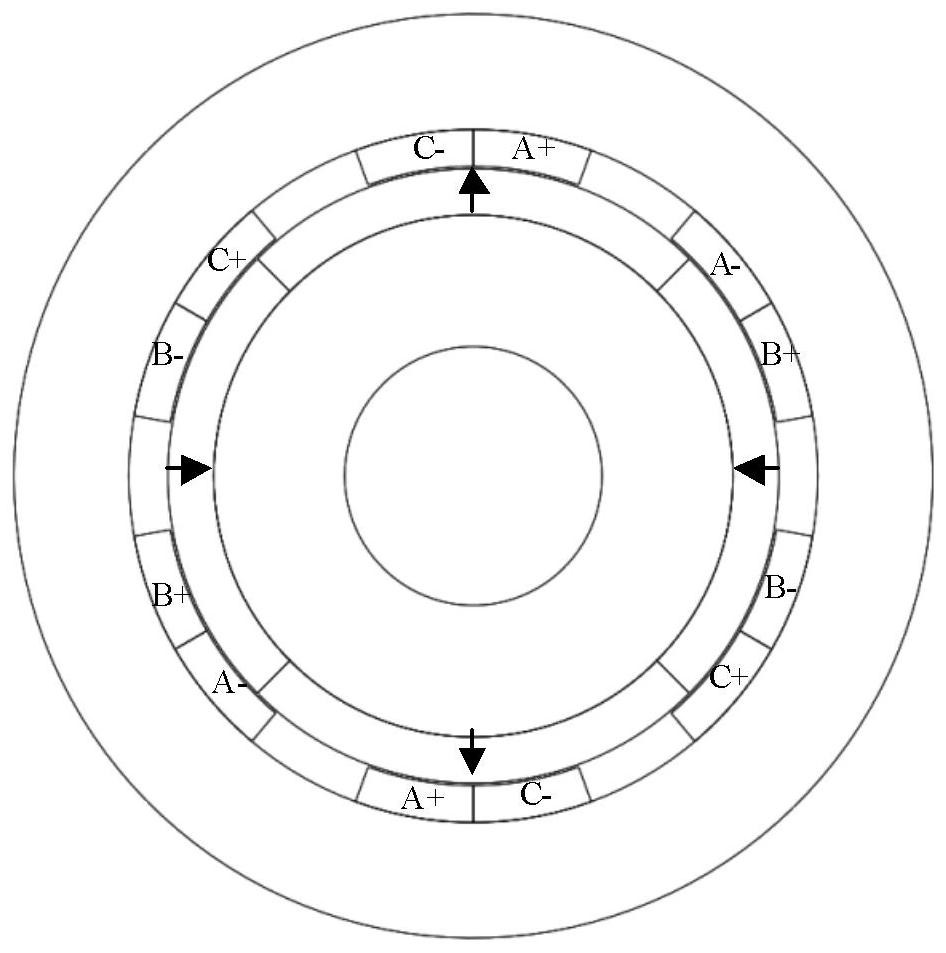
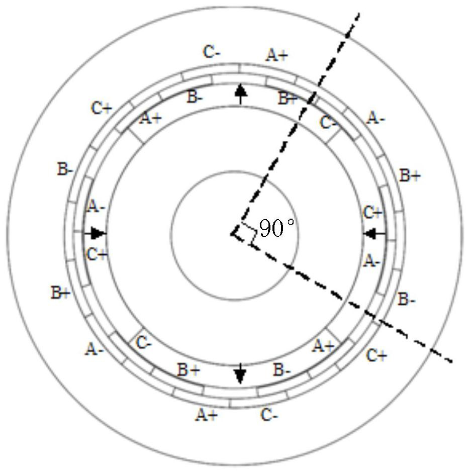
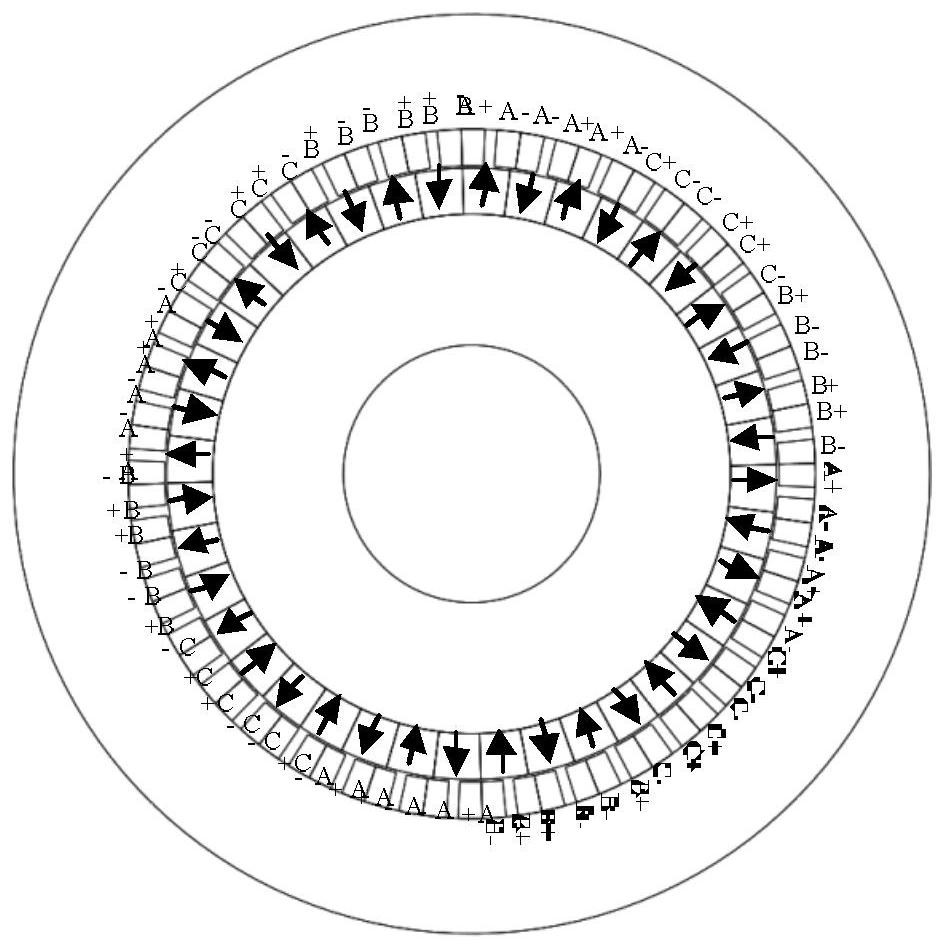
[0077] The stator includes an armature core and two sets of armature windings, the two sets of armature windings are three-phase fractional slot concentrated windings, the armature core is a slotless structure, and the armature windings are an epoxy resin potting structure. The two sets of armature windings are stacked radially along the armature core, and both...

specific Embodiment approach 2

[0084] Embodiment 2: The dual concentrated winding permanent magnet synchronous motor described in this embodiment includes two stators and a rotor arranged in an axial direction, the rotor is located between the two stators, and an air gap is formed between the stator and the rotor. The rotor includes a rotor core and a plurality of permanent magnets, and the plurality of permanent magnets are evenly fixed on the two air gap sides of the rotor core in an alternate arrangement of N and S poles. The rotor is a surface-mounted permanent magnet structure, an embedded permanent magnet structure, or Halbach permanent magnet array structure.

[0085] The stator includes an armature core and an armature winding, the armature winding is a three-phase fractional slot concentrated winding, and the corresponding phases of the armature windings on the two stators are connected in series, and the armature core is in the first structure or the second structure, They are as follows:

[0086...

specific Embodiment approach 3

[0096] Embodiment 3: The double concentrated winding permanent magnet synchronous motor described in this embodiment includes a stator and two rotors arranged along the axial direction, the stator is located between the two rotors, and there is an air gap between the stator and the rotor. The rotor includes a rotor core and a plurality of permanent magnets. The plurality of permanent magnets are evenly fixed on the air gap side of the rotor core in an alternate arrangement of N and S poles. The rotor is a surface-mounted permanent magnet structure, an embedded permanent magnet structure, or a Halbach permanent magnet. array structure.

[0097] The stator includes an armature core and two sets of armature windings. The two sets of armature windings are both three-phase fractional slot concentrated windings or annular windings. The corresponding phases of the two sets of armature windings are connected in series, and the armature cores are in the first structure. or the second s...


PUM


Abstract

A double concentrated winding permanent magnet synchronous motor relates to the technical field of motors. The invention is to solve the problem that the conventional fractional slot concentrated winding has a large harmonic content of the magnetomotive force, which is easy to cause irreversible demagnetization of the permanent magnet. And large magnetomotive force harmonics will cause torque fluctuations, reducing the low-speed stability of the motor. The invention includes two sets of armature windings. Both sets of armature windings are fractional slot concentrated windings and are arranged on the air gap side of the stator core. Each set of armature windings occupies one layer, and the two sets of armature windings are connected in series correspondingly. There is a phase difference between the corresponding phases of the sleeve windings. The invention reduces the harmonic content of the combined magnetomotive force and electromotive force of the two sets of armature windings by causing the corresponding phase dislocation of the two sets of armature windings to generate a phase difference, so that the eddy current loss of the rotor permanent magnet is reduced, and the torque fluctuation of the motor is reduced , good low-speed stability.

Description

technical field [0001] The invention belongs to the technical field of motors. Background technique [0002] There is only one set of windings on the stator of the traditional fractional-slot concentrated winding permanent magnet synchronous motor. This type of winding usually winds one coil on each tooth of the stator core, and there is no overlap between the coils. In this way, the length of the winding end can be effectively reduced, the copper loss of the stator can be reduced, the reliability of the winding can be improved, and the manufacturing cost of the motor can be reduced. At the same time, the positioning torque of the motor is small and the torque density is high. Therefore, fractional-slot concentrated-winding permanent magnet synchronous motors have been widely used. [0003] However, due to the large harmonic content of magnetomotive force in the concentrated winding of fractional slots, when the energization frequency of the motor winding is high and the o...

Claims


Application Information

Patent Timeline
Patent Type & Authority Patents(China)
IPC IPC(8): H02K21/24H02K1/16
CPCH02K21/24H02K1/165
Inventor 寇宝泉葛庆稳宋得雪黄昌闯
Owner HARBIN INST OF TECH
Why Eureka
Try Eureka