
Natural circulation-free control method of on-load voltage regulating transformer without transition resistance

A voltage regulating transformer, no transition technology, applied in the field of transformers, can solve the problems of high control precision at the time of voltage regulation, and the short circuit in the process of on-load voltage regulation is not really solved, and the effect of avoiding the short circuit problem is achieved.

Active Publication Date: 2022-07-05
YANGZHOU HUADING ELECTRIC APPLIANCE
View PDF2 Cites 0 Cited by
  • Summary
  • Abstract
  • Description
  • Claims
  • Application Information

AI Technical Summary

Problems solved by technology

[0004] Another solution in the existing technology is to remove the transition resistor, and ensure that the short-circuit time during the voltage regulation process is short enough by accurately selecting the voltage regulation time. The premise is assuming that the speed of the power electronic switch in the process of voltage regulation is fast enough, and a short-term short circuit will not have a great impact on the system, and it does not really solve the problem of short circuit in the process of on-load voltage regulation

Method used


Image

  • Natural circulation-free control method of on-load voltage regulating transformer without transition resistance
  • Natural circulation-free control method of on-load voltage regulating transformer without transition resistance
  • Natural circulation-free control method of on-load voltage regulating transformer without transition resistance

Examples


Embodiment Construction

[0037] The technical solutions in the embodiments of the present invention will be clearly and completely described below with reference to the accompanying drawings in the embodiments of the present invention. Obviously, the described embodiments are only a part of the embodiments of the present invention, but not all of the embodiments. Based on the embodiments of the present invention, all other embodiments obtained by those of ordinary skill in the art without creative efforts shall fall within the protection scope of the present invention.

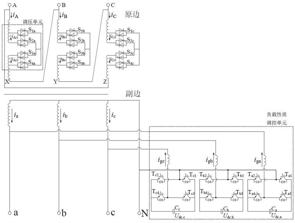
[0038] refer to figure 1 , an on-load voltage regulating transformer without transition resistance provided by the present invention, its topology structure includes: each voltage regulating unit of each phase contains four power electronic switches (taking phase A as an example, the first switch S 1a , the second switch S 2a , the third switch S 3a , the fourth switch S 4a ), each switch is composed of two anti-parallel thyristors...


PUM


Abstract

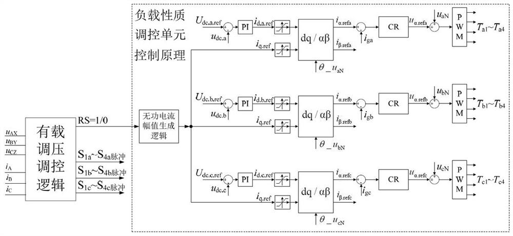
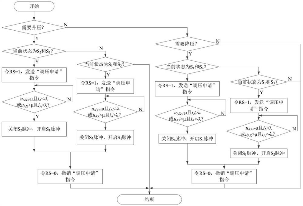
The invention discloses a natural non-circulating current control method for an on-load voltage regulating transformer without transition resistance, comprising the following steps: Step 1. Divide the possible conduction states of each power electronic switch in a voltage regulating unit into a secondary voltage of the transformer in a steady state Conduction state 1, conduction state 2, and conduction state 3 that increase in turn; step 2, collect the voltage and current of the primary side, and judge whether “boost” or “step-down” is needed according to the calculated RMS value of the voltage; step 3. If "step-up" or "step-down" is required, adjust the reactive current command of the load property control unit; step 4. Continuously check the voltage and current status of the primary side of the transformer, when both meet the "natural no circulating current" condition. When switching conditions, the corresponding state switching process is executed; the present invention can solve the short-circuit problem in the process of on-load voltage regulation without transition resistance, and at the same time can avoid the connection of the transition resistance in the process of on-load voltage regulation. losses and output voltage "sags" or "swells".

Description

technical field [0001] The invention relates to the technical field of transformers, in particular to an on-load voltage regulating transformer. Background technique [0002] At present, the most common solution in the application of on-load voltage regulating transformers is to use a mechanical switch to adjust the tap of the transformer, but the shortcomings of this solution bring many problems to practical applications, such as the short life of the mechanical switch and the later failure rate. high, making the device less maintainable. Compared with mechanical switches, power electronic switches have the advantages of fast response speed and long life. For this reason, the application of power electronic switches to on-load voltage regulating transformer devices has become a research hotspot in recent years. Among them, how to avoid the short-circuit phenomenon in the voltage regulation process of the on-load voltage regulating transformer based on power electronic devi...

Claims


Application Information

Patent Timeline
Patent Type & Authority Patents(China)
IPC IPC(8): H02P13/06H02J3/16H01F29/04H01F27/42
CPCH02P13/06H02J3/16H01F29/04H01F27/42Y02E40/30
Inventor 杨树德仰慧蔡长虹高雄鹰周鑫
Owner YANGZHOU HUADING ELECTRIC APPLIANCE
Learn More