
Novel breathing machine pipeline and breathing machine thereof

A ventilator and pipeline technology, applied in the field of ventilators, can solve problems such as pollution, easy pollution of the surrounding ward environment, and increased incidence of ventilator-associated pneumonia

Active Publication Date: 2021-08-27
HUNAN VENTMED MEDICAL TECH CO LTD
View PDF16 Cites 2 Cited by
  • Summary
  • Abstract
  • Description
  • Claims
  • Application Information

AI Technical Summary

Problems solved by technology

There is a water collection cup in the middle of the existing ventilator pipeline to collect condensed water. When the condensed water reaches a certain amount, it must be cleaned up in time, otherwise this humid environment is easy to colonize bacteria. The condensed water is an excellent bacterial bank, and pathogenic bacteria are easy to The parasitic reproduction here will increase the airway resistance and affect the patient's ventilation. At the same time, the condensed water stays for too long, which is conducive to bacterial reproduction. It may increase the incidence of ventilator-associated pneumonia and increase the mortality of patients by flowing to the patient's airway.
[0004] When the existing ventilator removes the water collection cup, the condensed water in the water collection cup may contain pathogenic bacteria and easily pollute the local environment, medical staff, surrounding patients, and cause nosocomial infection
[0005] In order to avoid backflow of condensed water, clinical medical staff need to wear gloves, and manually remove the water collecting cup to dump the condensed water every once in a while, and pour it into the trash can, and the trash can is covered with a lid, which is a huge workload; In the intensive care unit, it is easy to forget to replace the condensed water when the work is busy, and it is necessary to remind in time; when it is dumped, it may cause infection of the staff and environmental pollution, and it is easy to pollute the environment of the surrounding wards; because some equipment is removed from the bottle, the air pressure in the ventilator pipeline fluctuates

Method used


Image

  • Novel breathing machine pipeline and breathing machine thereof
  • Novel breathing machine pipeline and breathing machine thereof
  • Novel breathing machine pipeline and breathing machine thereof

Examples


Embodiment 1

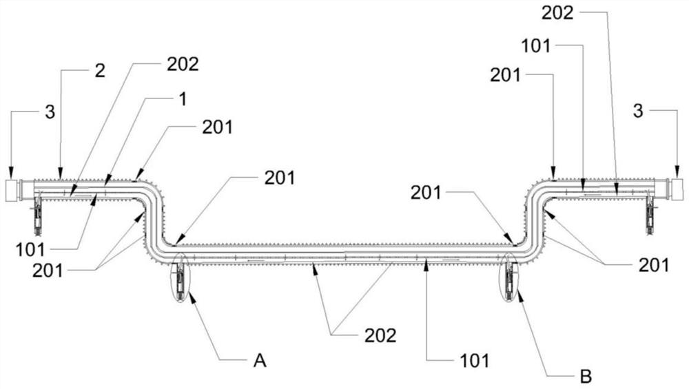
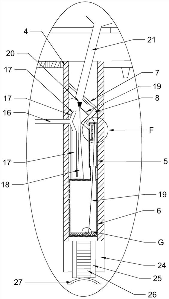
[0041] refer to Figure 1-11 , a novel ventilator circuit, including a ventilator circuit and a ventilator branch circuit.

[0042] The pipeline of the ventilator includes a built-in tube 1 and an external tube 2, and the built-in tube 1 and the external tube 2 form a "U"-shaped structure.

[0043] The built-in pipe 1 is a flexible pipe, and several through holes 101 are provided on all transverse pipelines of the built-in pipe 1; They are screwed and connected with each other, and the soft tubes and hard joints 201 are connected with each other to form the external tube 2. The bottom surface of the upper horizontal pipeline of the external tube 2 is an inclined surface 202 inclined towards the inside, and the bottom surface of the lower horizontal pipeline of the external tube 2 is an inclined surface 202 inclined towards the outer side. A joint 3 is provided, and the air passage in the joint 3 communicates with the built-in tube 1 and the external tube 2 .

[0044] The br...

Embodiment 2

[0053] Such as Figure 12-13 As shown, two ventilator branch pipelines are respectively fixed in the longitudinal pipelines on both sides of the external tube 2, and are arranged symmetrically with respect to the center line of the ventilator pipeline. A curing shell 28 is provided on the outer wall of the longitudinal pipeline at each ventilator branch pipeline position. All the other structures are the same as in Example 1.

[0054] A ventilator includes the novel ventilator pipeline.

[0055] Working principle of the present invention is:

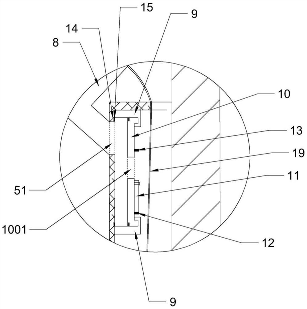
[0056] In normal state, such as Figure 1-5 As shown, the condensed water flows into the slope 202 from the through hole 101, and then flows into the two ventilator branch pipelines below. Collection chamber 1 5 and condensed water collection chamber 2 6 (at this time, the non-return side frame 9 and the non-return side buckle 10 are snapped together), which realizes the collection of condensed water. At this time, the floating ball ...


PUM


Abstract

The invention discloses a novel breathing machine pipeline. The novel breathing machine pipeline comprises a breathing machine pipeline and a breathing machine branch pipeline, the breathing machine pipeline is an integrated U-shaped pipe, the breathing machine branch pipeline is arranged below the breathing machine pipeline, and the breathing machine pipeline is used in a breathing machine. The novel breathing machine pipeline is an integrated pipe, the integrated pipe achieves collection, backflow prevention and instant atomization of condensate water in the pipe, and the situation that bacteria breed due to the fact that the condensate water collected by an existing breathing machine pipeline is placed for several days is avoided; according to the breathing machine pipeline, backflow prevention of condensate water in the breathing machine can be achieved under the normal condition, and backflow prevention of the condensate water in the breathing machine can also be achieved under the extreme conditions of bending, inclining, overall 180-degree inversion and the like; and condensate water enters the breathing machine branch pipeline, instant atomization can be achieved, then the condensate water is sprayed into the built-in pipe, it is avoided that the condensate water is placed for a long time to breed bacteria, the condensate water is recycled, the gas atomization effect is achieved, and the condensate water is treated.

Description

technical field [0001] The invention relates to the technical field of ventilators, in particular to a novel ventilator pipeline and a ventilator thereof. Background technique [0002] In modern clinical medicine, the ventilator, as an effective means of artificially replacing the spontaneous ventilation function, has been widely used in respiratory failure caused by various reasons, anesthesia respiratory management during major surgery, respiratory support treatment and emergency resuscitation. It occupies a very important position in the field of modern medicine. Ventilator is a vital medical equipment that can prevent and treat respiratory failure, reduce complications, save and prolong the life of patients. [0003] The air source of the ventilator is conducted to the patient through the ventilator tube. There is a water collection cup in the middle of the existing ventilator pipeline to collect condensed water. When the condensed water reaches a certain amount, it mu...

Claims


Application Information

Patent Timeline
Patent Type & Authority Applications(China)
IPC IPC(8): A61M16/08A61M16/16A61M16/00
CPCA61M16/0808A61M16/16A61M16/0816A61M16/0003
Inventor 刘哲唐聪能郑其昌周磊粟锦平
Owner HUNAN VENTMED MEDICAL TECH CO LTD
Learn More