A polishing treatment device for hardware processing
A technology for processing devices and hardware, which is applied in the direction of grinding/polishing safety devices, metal processing equipment, grinding/polishing equipment, etc., which can solve the inconvenience of cleaning hardware debris, inconvenient collection of hardware pull cards, and inconvenient hardware pull card flipping Surface and other problems to achieve the effect of enhancing the polishing effect
- Summary
- Abstract
- Description
- Claims
- Application Information
AI Technical Summary
Problems solved by technology
Method used
Image
Examples
Embodiment 1
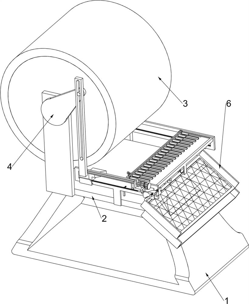
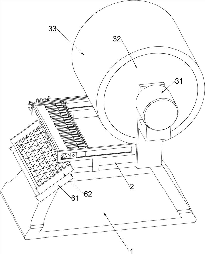
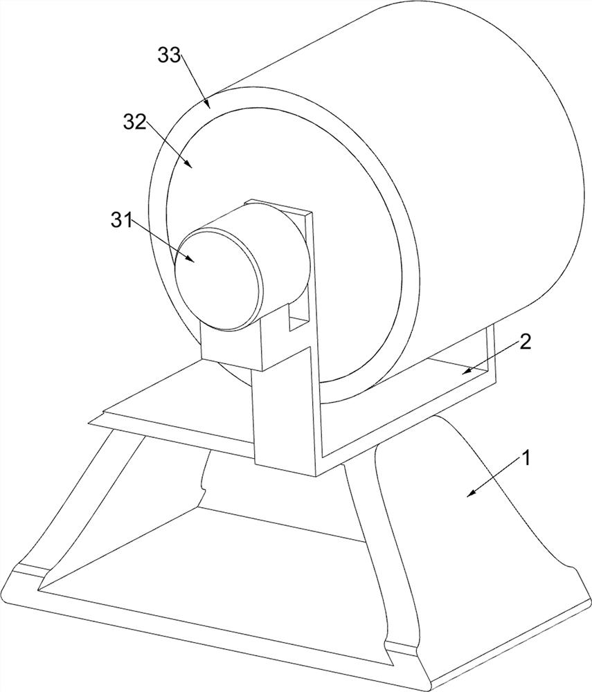
[0035] A polishing treatment device for hardware processing, such as Figure 1-6As shown, it includes a support base 1, a first support frame 2, a polishing assembly 3 and a push assembly 4, a first support frame 2 is fixedly connected above the support base 1, and a polishing assembly 3 is arranged on the upper part of the first support frame 2. A push assembly 4 is provided between the front and rear sides of a support frame 2, and the push assembly is connected with the polishing assembly. The polishing assembly 3 includes a motor 31, a first rotating roller 32 and a friction ring 33. The motor 31 is installed on the upper rear side of the first support frame 2, and the first rotating roller 32 is rotatably installed on the inner upper part of the first support frame 2. The rear end of the first rotating roller 32 is fixedly connected to the front end of the output shaft of the motor 31 , and a friction ring 33 is fixedly connected to the first rotating roller 32 inside the...
Embodiment 2
[0039] On the basis of Example 1, such as Figure 6-9 As shown, it also includes an overturn assembly 5, which is arranged on the second support frame 41, and the overturn assembly 5 includes a rotating lever 51, a first limit lever 52, a support block 521, a return spring 522, and a wedge-shaped stopper. 53. The second limit rod 54, the push frame 55, the telescopic spring 551 and the guide groove plate 56, the front side of the slide rail plate 43 is fixedly welded with the rotary lever 51, and the right side of the second support frame 41 on the front side is fixedly connected with the second A limit rod 52, the first limit rod 52 is slidably connected with a support block 521, and a return spring 522 is connected between the support block 521 and the second support frame 41 on the front side, and the second support frame 41 on the front side The left part of the side is fixedly connected with a wedge-shaped block 53, and the second support frame 41 front right part of the ...
Embodiment 3
[0043] On the basis of Example 2, such as Figure 10-12 As shown, a toggle assembly 7 is also included, and the toggle assembly 7 is arranged on the first support frame 2, and the toggle assembly 7 includes a third support frame 71, a fixed guide frame 72, a swing plate 73 and a second torsion spring 74 A third support frame 71 is fixedly connected to the front side above the first support frame 2, and a fixed guide frame 72 is fixedly connected to the rear upper side of the third support frame 71. The fixed guide frame 72 is fixedly connected with a rotating rod and a swing plate 73 The upper part of the upper part is rotatably connected on the rotating rod of the fixed guide frame 72, and the rotating rod on the fixed guide frame 72 is covered with a second torsion spring 74, and one end of the second torsion spring 74 is affixed with the rotating rod on the fixed guide frame 72. The other ends of the two torsion springs 74 are fixedly connected to the swing plate 73 .
[0...
PUM
 Abstract
Description
Claims
Application Information
 - R&D
- Intellectual Property
- Life Sciences
- Materials
- Tech Scout
- Unparalleled Data Quality
- Higher Quality Content
- 60% Fewer Hallucinations
Browse by: Latest US Patents, China's latest patents, Technical Efficacy Thesaurus, Application Domain, Technology Topic, Popular Technical Reports.
© 2025 PatSnap. All rights reserved.Legal|Privacy policy|Modern Slavery Act Transparency Statement|Sitemap|About US| Contact US: help@patsnap.com


