
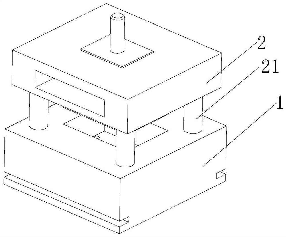
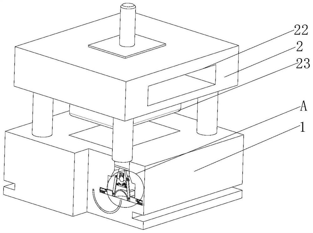
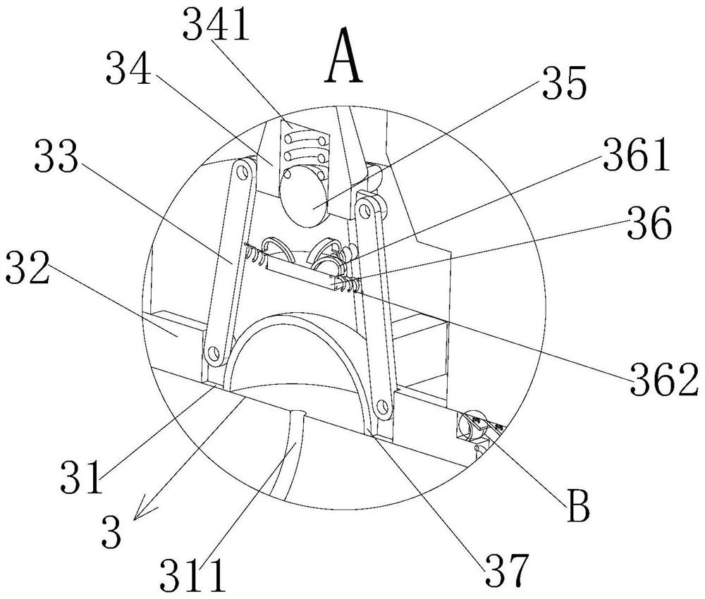
Injection mold with piston buffer structures at four corners

A buffer structure, injection mold technology, applied in coating and other directions, can solve the problems of reducing the production efficiency of injection parts, damage to small connecting parts, trouble in the mold opening process, etc., to reduce the rate of defective products, reduce air bubbles, and improve production quality. Effect

Active Publication Date: 2021-08-27
长兴优浩科技有限公司
View PDF7 Cites 2 Cited by
  • Summary
  • Abstract
  • Description
  • Claims
  • Application Information

AI Technical Summary

Problems solved by technology

Plastic products are widely used in industrial products. In the production process of some plastic parts, the finished product inside the injection mold will deform when the temperature changes, which makes the mold opening process more troublesome and may seriously It leads to damage to small connecting parts and reduces the production efficiency of injection molded parts. Therefore, we propose an injection mold with four-corner piston buffer structure to solve the above problems

Method used


Image

  • Injection mold with piston buffer structures at four corners
  • Injection mold with piston buffer structures at four corners
  • Injection mold with piston buffer structures at four corners

Examples


Embodiment Construction

[0026] The following will clearly and completely describe the technical solutions in the embodiments of the present invention with reference to the accompanying drawings in the embodiments of the present invention. Obviously, the described embodiments are only some, not all, embodiments of the present invention. Based on the embodiments of the present invention, all other embodiments obtained by persons of ordinary skill in the art without making creative efforts belong to the protection scope of the present invention.

[0027] see Figure 1-6 , the present invention provides a technical solution: an injection mold with piston buffer structure at four corners, including a lower template 1, a plurality of guide rods 21 are movably inserted on the surface of the lower template 1, and an auxiliary buffer mechanism 3 is provided at the bottom of the guide rods 21 , the lower formwork 1 is provided with a cavity 11, the side wall of the lower formwork 1 is provided with a pair of c...


PUM


Abstract

The invention discloses an injection mold with piston buffer structures at the four corners. The injection mold comprises a lower mold plate, a plurality of guide rods are movably inserted into the surface of the lower mold plate, auxiliary buffer mechanisms are arranged at the bottoms of the guide rods, a cavity is formed in the lower mold plate, a pair of clamping grooves are formed in the side wall of the lower mold plate, an upper mold plate is fixedly welded to the guide rods, a connecting shaft is fixedly connected to the upper mold plate, a driving groove is formed in the side wall of the upper mold plate, a mold core is fixedly connected to the bottom of the upper mold plate, a cooling groove is formed inside the mold core and communicates with the driving groove, and a cooling mechanism is fixedly connected to the bottom of the driving groove. Compared with the prior art, when the guide rods are stressed to move, ejector blocks can be pushed to move downwards, hinge rods can move, buffer rods are pushed to move in straight grooves, a buffer effect can be achieved through reset springs and extrusion springs, the situation that bubbles are generated in an injection molding part due to the fact that the guide rods move too fast is avoided, and the defective product rate of the injection molding part can be reduced.

Description

technical field [0001] The invention relates to the technical field of injection molds, in particular to an injection mold with four corners and a piston buffer structure. Background technique [0002] Plastic molds are tools that are matched with plastic molding machines in the plastic processing industry to give plastic products a complete configuration and precise dimensions. Due to the variety of plastics and processing methods, and the structures of plastic molding machines and plastic products, the types and structures of plastic molds are also varied. [0003] With the improvement of today's living standards, users have put forward higher requirements for the design of industrial products, making the current industrial design requirements for product quality higher and higher. Plastic products are widely used in industrial products. In the production process of some plastic parts, the finished product inside the injection mold will deform when the temperature changes...

Claims


Application Information

Patent Timeline
Patent Type & Authority Applications(China)
IPC IPC(8): B29C45/26B29C45/00B29C45/17B29C45/40B29C45/73
CPCB29C45/2602B29C45/0025B29C45/1756B29C45/4005B29C45/7337
Inventor 杉山好美
Owner 长兴优浩科技有限公司
Learn More