Large 3D printer rack machining tool

A 3D printer and rack technology, used in additive processing, metal processing equipment, processing platforms/substrates, etc., can solve the problem that tooling components cannot be made into large racks, saving production time, strong practicability, design reasonable effect

Pending Publication Date: 2021-08-27
宜兴市信拓智能装备制造有限公司
View PDF0 Cites 0 Cited by
  • Summary
  • Abstract
  • Description
  • Claims
  • Application Information

AI Technical Summary

Problems solved by technology

[0006] Purpose of the invention: the purpose of the present invention is to provide a large-scale 3D printer frame processing tooling, which solves the problem that the existing tooling parts cannot make a large-scale frame, and can stably fix the large-scale 3D printer frame to be produced, that is, it is compatible with finishing The equipment is used together to complete the efficient and precise processing of large racks

Method used


Image

  • Large 3D printer rack machining tool

Examples


Embodiment 1

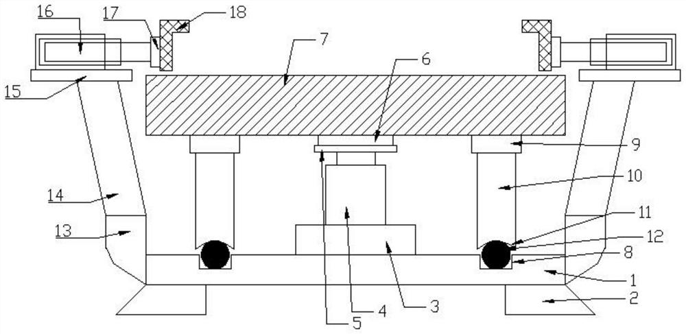
[0014] Such as figure 1 The shown large-scale 3D printer frame processing tooling includes a base plate 1, several supporting legs 2 arranged on one side of the base plate 1, and a motor mounting seat 3 arranged on the other side of the base plate 1, and a motor mounting seat 3 arranged on the base plate 1. The motor 4 on the top, and the connecting plate 5 arranged at one end of the motor 4, and the supporting block 6 arranged on one side of the connecting plate 5, and the working table 7 arranged on one side of the supporting block 6, and arranged on the other side of the base plate 1 and located at the motor The circular limit groove 8 of the mounting seat 3 outer layer, and several connection blocks 9 arranged on one side of the workbench 7, and the vertical support rods 10 respectively arranged on one side of the connection block 9, and respectively arranged on the vertical support rods 10 A semicircular groove 11 on one end surface, and several balls 12 arranged in the c...

Embodiment 2

[0016] Such as figure 1 The shown large-scale 3D printer frame processing tooling includes a base plate 1, several supporting legs 2 arranged on one side of the base plate 1, and a motor mounting seat 3 arranged on the other side of the base plate 1, and a motor mounting seat 3 arranged on the base plate 1. The motor 4 on the top, and the connecting plate 5 arranged at one end of the motor 4, and the supporting block 6 arranged on one side of the connecting plate 5, and the working table 7 arranged on one side of the supporting block 6, and arranged on the other side of the base plate 1 and located at the motor The circular limit groove 8 of the mounting seat 3 outer layer, and several connection blocks 9 arranged on one side of the workbench 7, and the vertical support rods 10 respectively arranged on one side of the connection block 9, and respectively arranged on the vertical support rods 10 The semicircular groove 11 on one end face, and the several balls 12 that are arran...


PUM


Abstract

The invention belongs to the technical field of 3D printer application, and particularly discloses a large 3D printer rack machining tool. The large 3D printer rack machining tool comprises a bottom plate, a plurality of supporting legs, a motor mounting base, a motor, a connecting plate, a supporting block, a working table, a circular limiting groove, a plurality of connecting blocks, a vertical supporting rod, a semicircular groove, a plurality of balls and the like. The large 3D printer rack machining tool has the following beneficial effects: firstly, the problem that a large rack cannot be manufactured through an existing tool part is solved, the large 3D printer rack to be manufactured can be stably fixed, that is, the large 3D printer rack machining tool is used in cooperation with finish machining equipment, and efficient and accurate machining operation of the large rack is completed; and secondly, the design is reasonable, intelligent automatic control can be achieved through the motor and a set of air cylinders, manual control is not needed, the production and manufacturing time is saved, meanwhile, overhaul and maintenance are convenient, the service life is long, and the practicability is high.

Description

technical field [0001] The invention belongs to the technical field of 3D printer applications, and in particular relates to a processing tool for a large 3D printer frame. Background technique [0002] 3D printing (3DP) is a kind of rapid prototyping technology, also known as additive manufacturing. It is based on digital model files, using powdered metal or plastic and other bondable materials to construct by layer-by-layer printing. technology of objects. [0003] 3D printing is usually achieved using digital technology material printers. It is often used to make models in the fields of mold manufacturing and industrial design, and is gradually used in the direct manufacture of some products. There are already parts printed using this technology. This technology is widely used in jewelry, footwear, industrial design, architecture, etc. , engineering and construction (AEC), automotive, aerospace, dental and medical industries, education, geographic information systems, c...

Claims


Application Information

Patent Timeline
IPC IPC(8): B29C64/245B29C64/25B33Y30/00
CPCB33Y30/00B29C64/245B29C64/25
Inventor 裴跃新裴杨
Owner 宜兴市信拓智能装备制造有限公司
Why Eureka
Try Eureka