Diagnostic system and diagnostic method for valve type thermostat and vehicle

A diagnostic system and diagnostic method technology, applied in the direction of engine cooling, machine/engine, coolant flow control, etc., can solve problems such as unnecessary response, false alarm, and unclear cause of failure, so as to reduce engine fuel consumption, Avoid over-temperature damage and improve work efficiency

A diagnostic system and diagnostic method technology, applied in the direction of engine cooling, machine/engine, coolant flow control, etc., can solve problems such as unnecessary response, false alarm, and unclear cause of failure, so as to reduce engine fuel consumption, Avoid over-temperature damage and improve work efficiency

CN113309604AActive Publication Date: 2021-08-27UNITED AUTOMOTIVE ELECTRONICS SYST

Image

  • Diagnostic system and diagnostic method for valve type thermostat and vehicle
  • Diagnostic system and diagnostic method for valve type thermostat and vehicle
  • Diagnostic system and diagnostic method for valve type thermostat and vehicle

Examples


Embodiment Construction

[0038] The diagnostic system, diagnostic method and vehicle of the valve thermostat proposed by the present invention will be further described in detail below in conjunction with the accompanying drawings and specific embodiments. The advantages and features of the present invention will be more apparent from the following description. It should be noted that all the drawings are in very simplified form and use imprecise scales, which are only used to facilitate and clearly assist the purpose of the embodiments of the present invention.

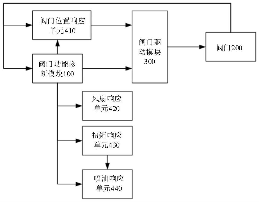
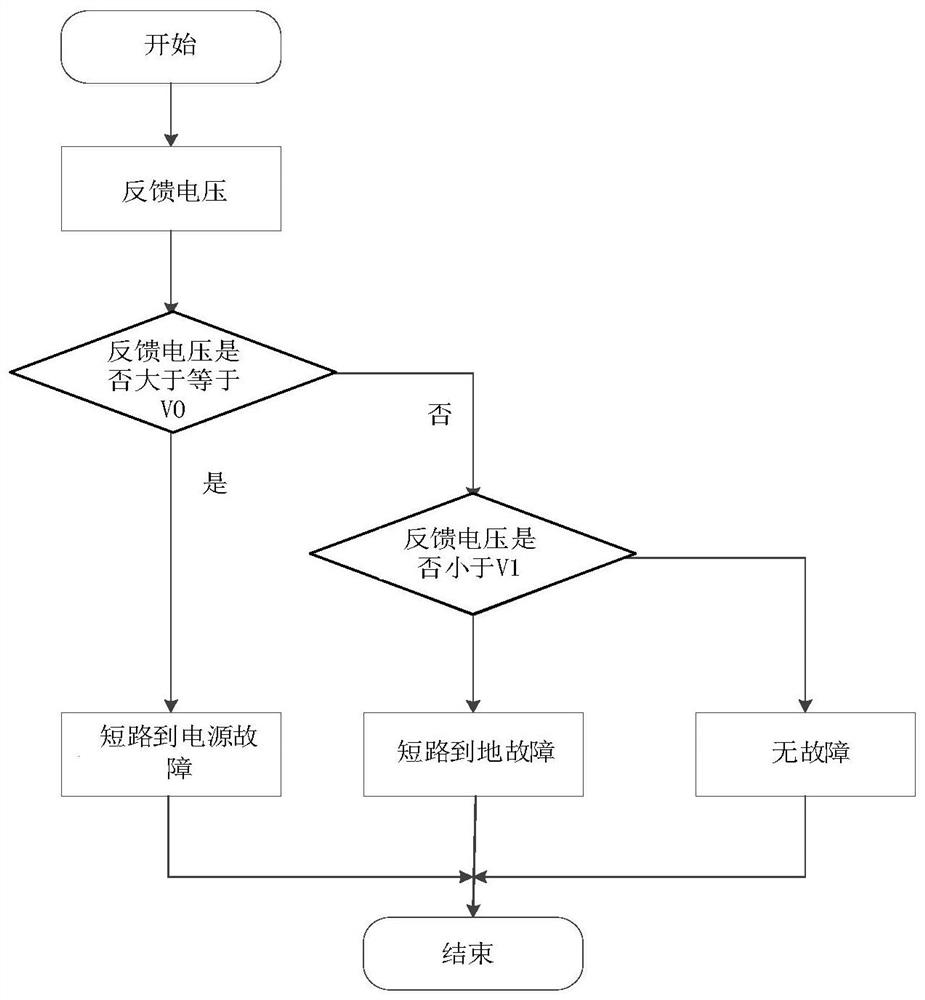
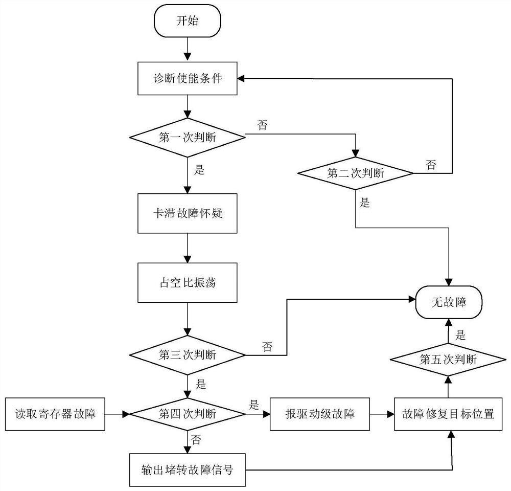
[0039] In this embodiment, the valve-type thermostat is a component that helps the engine body to dissipate heat. For example, it is a multi-way valve-type electronic thermostat, which includes a valve. The valve can be a multi-way valve. On the liquid path, the mutual coupling of different cooling circuits can be realized. The valve of the valve thermostat can be controlled by the output of the driver stage. The driving stage refers to th...


PUM


Abstract

The invention provides a diagnostic system and diagnostic method for a valve type thermostat and a vehicle. By means of the diagnosis system and the diagnosis method, whether a valve of the valve type thermostat breaks down or not can be diagnosed, the fault is reported or not according to the diagnosis result, if it is diagnosed that a suspected locked-rotor fault exists, repair is tried before the locked-rotor fault is reported, if repair succeeds, the locked-rotor fault is not reported, and false alarm is avoided. In addition, response can be made according to reported faults, so that an engine is maintained in a safe temperature range, and the engine is prevented from being damaged due to over-temperature. The vehicle comprises the engine provided with the valve type thermostat and the diagnostic system of the valve type thermostat.

Description

technical field [0001] The invention relates to the technical field of engines, in particular to a diagnosis system, a diagnosis method and a vehicle of a valve type thermostat. Background technique [0002] During the use of the internal combustion engine, about 30% of the heat is taken away by the coolant. In order to avoid the engine temperature from being too high or too low and improve the energy utilization rate of the internal combustion engine, the industry has begun to use valve-type thermostats to help the engine body dissipate heat. . Valve-type thermostats often use multi-way valves, which can realize the mutual coupling of different cooling circuits and reasonably distribute the coolant flow of different cooling circuits, so as to realize the optimal management of engine heat. It has the advantages of fast response and precise control of engine coolant temperature. The characteristics improve engine efficiency and reduce fuel consumption, so it is favored by ma...

Claims


Application Information

Patent Timeline
27 Aug 2021
Publication
CN113309604A
IPC
F01P11/14; F01P7/16
CPC
F01P11/14; F01P7/16; F01P2007/146
Inventors
张柳; 方强