
Double-seal piston type flow and pressure regulating valve

A piston-type, pressure-regulating valve technology, applied in the direction of valve lift, valve details, valve devices, etc., can solve problems such as noise, unstable operation, vibration, etc., and achieve the effect of simple device structure, good sealing effect, and convenient use

Pending Publication Date: 2021-08-27
OUGUAN VALVE TECH
View PDF0 Cites 0 Cited by
  • Summary
  • Abstract
  • Description
  • Claims
  • Application Information

AI Technical Summary

Problems solved by technology

[0003] The current flow regulating and pressure regulating valves often have problems such as unstable operation, noise, vibration, cavitation, and serious damage to the sealing position during operation, and the existing flow regulating and pressure regulating valves all adopt a single-seal structure. As a result, once there is a problem with the sealing structure, the valve will inevitably be unusable, which will affect people's life, production, etc.

Method used


Image

  • Double-seal piston type flow and pressure regulating valve
  • Double-seal piston type flow and pressure regulating valve
  • Double-seal piston type flow and pressure regulating valve

Examples


Embodiment 1

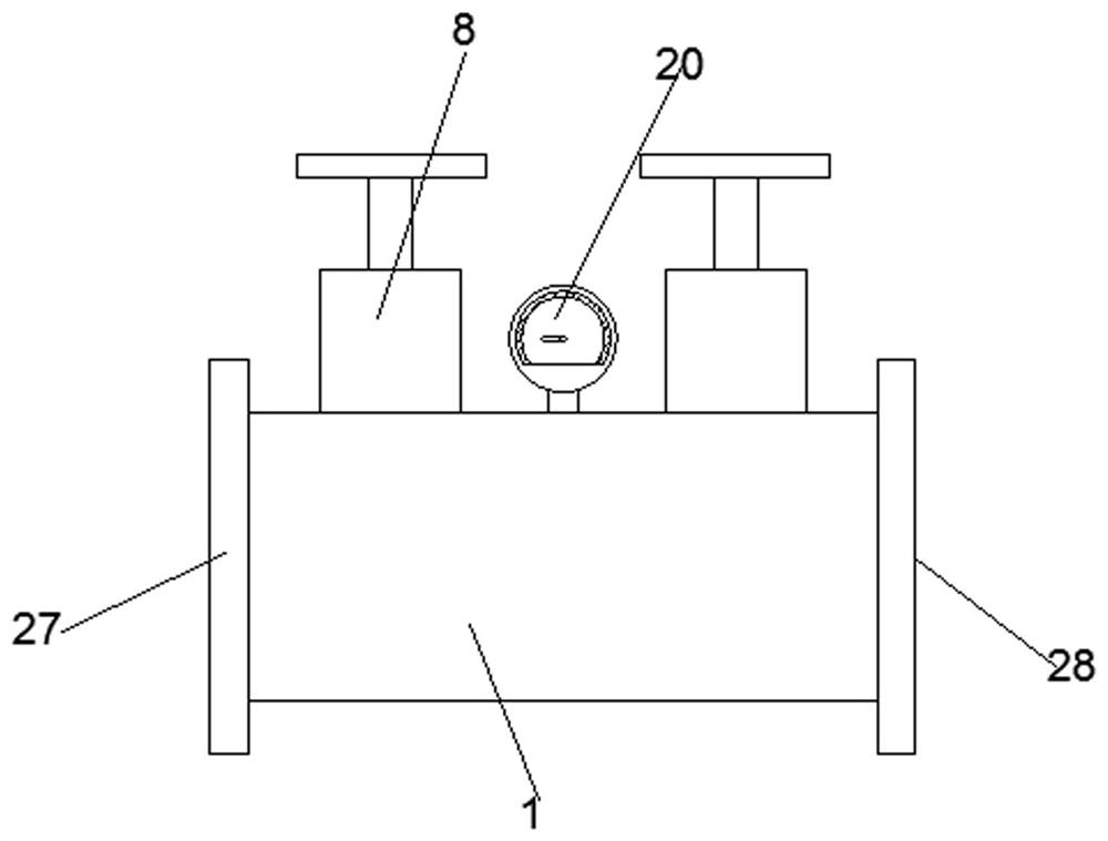
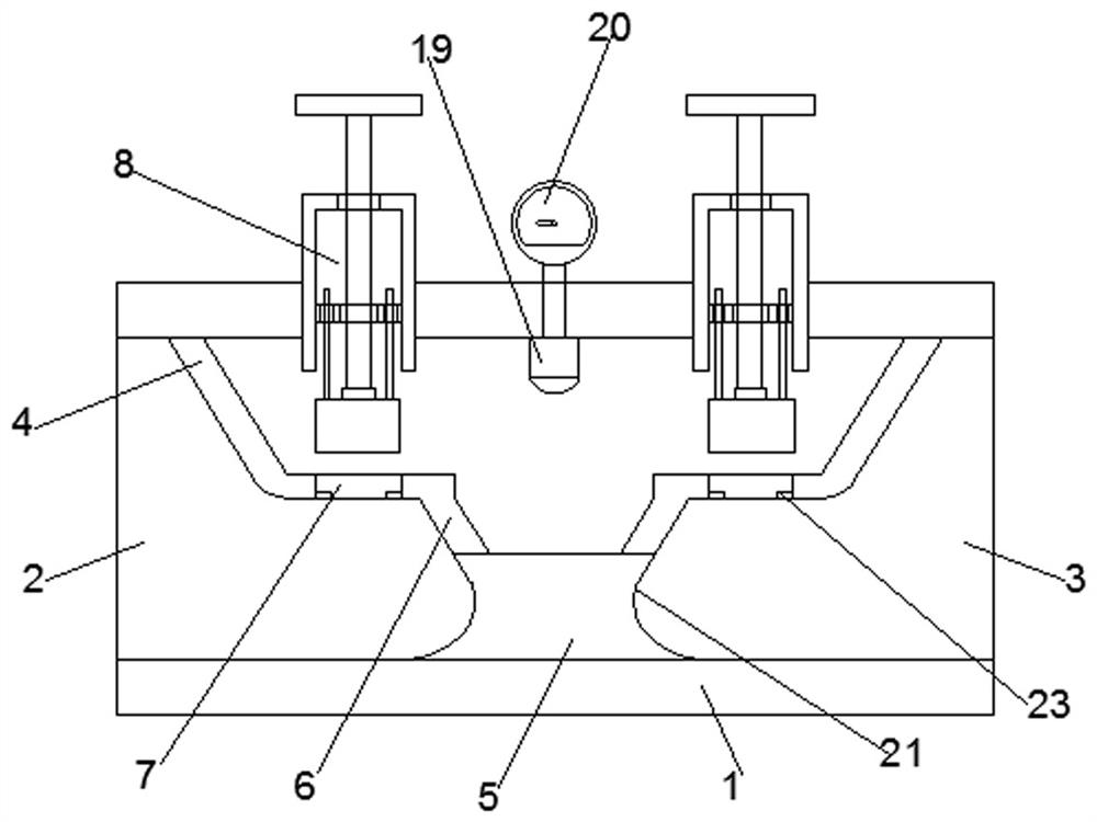
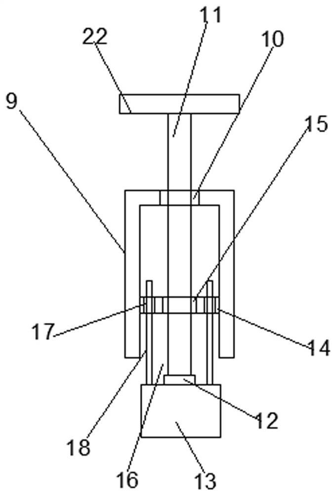
[0032] see Figure 1-4 , according to an embodiment of the present invention, a double-sealed piston-type flow regulating and pressure regulating valve includes a valve body 1, the two ends of the valve body 1 are respectively provided with a liquid inlet 2 and a liquid outlet 3, and the valve body 1 The top of the inner wall is symmetrically provided with an upper arc guide plate 4, and the center of the inner wall bottom of the valve body 1 is fixed with a fixed base 5, and both sides of the fixed base 5 are provided with a lower arc guide plate 6, so An opening 7 is provided between the upper arc-shaped deflector 4 and the lower arc-shaped deflector 6, and an adjustment sealing device 8 is provided on the opening 7, and the adjustment sealing device 8 includes a connecting cylinder 9. A threaded hole 10 is provided on the connecting cylinder 9, and a threaded rod 11 runs through the threaded hole 10. The bottom end of the threaded rod 11 is connected with a sealing block 13...

Embodiment 2

[0035] Such as Figure 1-4As shown, the valve body 1 is provided with a pressure sensor 19 between the adjustment sealing device 8, and the pressure sensor 19 is connected with a pressure gauge 20, which is convenient for detecting the pressure in the valve body 1; the fixed Both sides of the outer wall of the base 5 are provided with arc-shaped plates 21, which play the role of diversion to the water flow; The rotation of the rod 11; the opening 7 is provided with a positioning ring 23, which is convenient for the positioning of the sealing block 13; the sealing block 13 includes a fixed bottom plate 24, and an elastic backing plate 25 is arranged on the fixed bottom plate 24, and the elastic The backing plate 25 is provided with an upper fixing plate 26, which can reduce the water pressure it receives and increase the sealing performance; the two ends of the liquid inlet 2 and the liquid outlet 3 are respectively provided with a mounting plate 27 and a mounting plate 2 28, ...


PUM


Abstract

The invention discloses a double-seal piston type flow and pressure regulating valve which comprises a valve body, wherein a liquid inlet and a liquid outlet are formed in two ends of the valve body respectively, upper arc-shaped flow guide plates are symmetrically arranged at the top of the inner wall of the valve body, a fixed base is fixedly arranged at the center of the bottom of the inner wall of the valve body, lower arc-shaped flow guide plates are arranged on two sides of the fixed base, openings are formed between the upper arc-shaped flow guide plates and the lower arc-shaped flow guide plates, adjusting sealing devices are arranged on the openings and comprise connecting cylinders, threaded holes are formed in the connecting cylinders, threaded rods are arranged in the threaded holes in a penetrating mode, the bottom end of the threaded rod is connected with a sealing block through a bearing sleeve, the sealing block is matched with the opening, and a fixing plate is fixedly arranged in the connecting cylinder. The device has the beneficial effects that the device is simple in structure and convenient to use, the water pressure can be adjusted from two sides respectively, the sealing effect is good, and when any one goes wrong, the other one can still work.

Description

technical field [0001] The invention relates to the technical field of valves, in particular to a double-seal piston type flow regulating and pressure regulating valve. Background technique [0002] Valves are devices used to control the direction, pressure, and flow of fluids in fluid systems; valves are control components in pipeline fluid delivery systems, and valves can be used to control air, water, steam, various corrosive media, mud, oil, etc. It is used to change the cross section of the channel and the flow direction of the medium, and has the functions of diversion, cut-off, throttling, check, diversion or overflow and pressure relief; the valve used for fluid control, From the simplest cut-off valve to various valves used in extremely complex automatic control systems, there are many varieties and specifications. [0003] The current flow regulating and pressure regulating valves often have problems such as unstable operation, noise, vibration, cavitation, and se...

Claims


Application Information

Patent Timeline
Patent Type & Authority Applications(China)
IPC IPC(8): F16K1/02F16K1/32F16K1/36F16K27/02F16K31/60F16K37/00F16K47/02F16K47/04
CPCF16K1/02F16K1/32F16K1/36F16K27/02F16K31/602F16K37/0091F16K47/023F16K47/04
Inventor 吴文川吴文忠林少峰
Owner OUGUAN VALVE TECH
Learn More