Check patentability & draft patents in minutes with Patsnap Eureka AI!

Robot-based roller detection system

A detection system and robot technology, applied in the direction of instruments, measuring devices, measuring instrument components, etc., can solve the problems of high mechanical precision and synchronization on both sides, affecting the straightness detection effect, and easy failure of equipment, etc., to achieve the detection work Compact and reliable, accurate and fast handling process, low labor intensity

Pending Publication Date: 2021-08-27
佛山市尼森投资有限公司
View PDF5 Cites 0 Cited by
  • Summary
  • Abstract
  • Description
  • Claims
  • Application Information

AI Technical Summary

Problems solved by technology

[0004] Although the above-mentioned patent application realizes the automatic detection of the concentrated load and straightness of the kiln roller rods, there are the following problems: 1) During the concentrated load detection, the roller rods are pressed from top to bottom by the linear module while rotating mechanism, and the rotating wheel of the rotating mechanism is generally a rubber wheel, which is very easy to be deformed or crushed, which directly affects the subsequent straight

Method used


Image

  • Robot-based roller detection system
  • Robot-based roller detection system
  • Robot-based roller detection system

Examples


Embodiment Construction

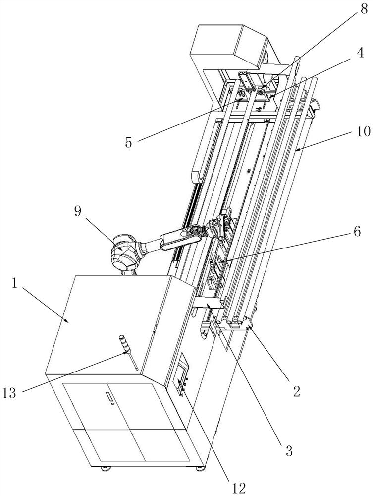
[0032] In the description of the present invention, it should be noted that for orientation words, such as the terms "center", "horizontal", "longitudinal", "length", "width", "thickness", "upper", "lower" , "Front", "Back", "Left", "Right", "Vertical", "Horizontal", "Top", "Bottom", "Inner", "Outer", "Clockwise", "Counterclockwise " and other indication orientations and positional relationships are based on the orientations or positional relationships shown in the drawings, and are only for the convenience of describing the present invention and simplifying the description, rather than indicating or implying that the device or element referred to must have a specific orientation, or in a specific orientation. The structure and operation should not be construed as limiting the specific protection scope of the present invention.

[0033] In addition, terms such as "first" and "second" are used for descriptive purposes only, and cannot be understood as indicating or implying rel...


PUM


Abstract

A robot-based roller detection system disclosed by the present invention comprises a rack, a feeding station, a discharging station, a detection station and a marking station are arranged on the rack, the detection station and the marking station are arranged side by side from front to back, a load detection device and a straightness detection device are arranged corresponding to the detection station, and the detection station is provided with a rotating mechanism used for driving a to-be-detected roller to rotate. The system is characterized in that the feeding station and the discharging station are both located on the front side of the rack, the discharging station is located over the feeding station, and a carrying robot is arranged on the rear side of the rack; the load detection device and the straightness detection device are located below the detection station, and a lifting limiting device used for limiting the position of the to-be-detected roller is arranged above the detection station. A rotating wheel cannot be crushed during concentrated load detection, and the labor intensity is lower.

Description

technical field [0001] The invention relates to the technical field of automatic detection, in particular to a robot-based roller rod detection system. Background technique [0002] As an important part of the transmission system of the continuous firing kiln, the straightness of the roller rod plays a vital role in the transmission of the fired products in the kiln. The straightness of the roll product directly affects the size of the position deviation of the fired product during the firing process in the kiln, the neatness of the fired product out of the furnace, the poor quality of the roll rod, and the large deviation of the product position, which can seriously cause the product Blocking the kiln, or even shutting down the line for maintenance, will cause huge losses. In addition, because the firing temperature of the roller kiln is high, the unit weight of the product is relatively large, so there is a high requirement for the load strength of the roller, which is as...

Claims


Application Information

Patent Timeline
IPC IPC(8): G01D21/02G01D11/00G01D11/16
CPCG01D21/02G01D11/00G01D11/16Y02P90/02
Inventor 杨国榜何军斌
Owner 佛山市尼森投资有限公司
Features
  • R&D
  • Intellectual Property
  • Life Sciences
  • Materials
  • Tech Scout
  • Unparalleled Data Quality
  • Higher Quality Content
  • 60% Fewer Hallucinations
Learn More