Large-stiffness specimen test device for double-array system based on electro-hydraulic servo
A technology of electro-hydraulic servo and test piece test, which is applied in the direction of measuring device, machine/structural component test, vibration test, etc. It can solve the problems of reducing the use efficiency and damage of test piece, so as to eliminate additional internal force and avoid damage to test piece , The effect of improving the efficiency of system testing
- Summary
- Abstract
- Description
- Claims
- Application Information
AI Technical Summary
Problems solved by technology
Method used
Image
Examples
Embodiment 1
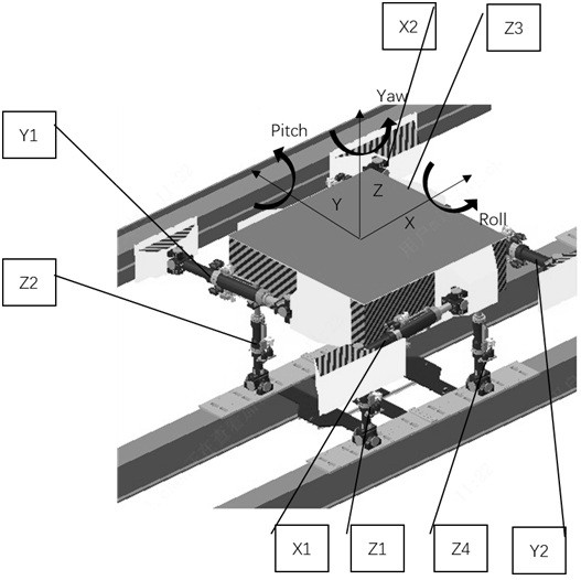
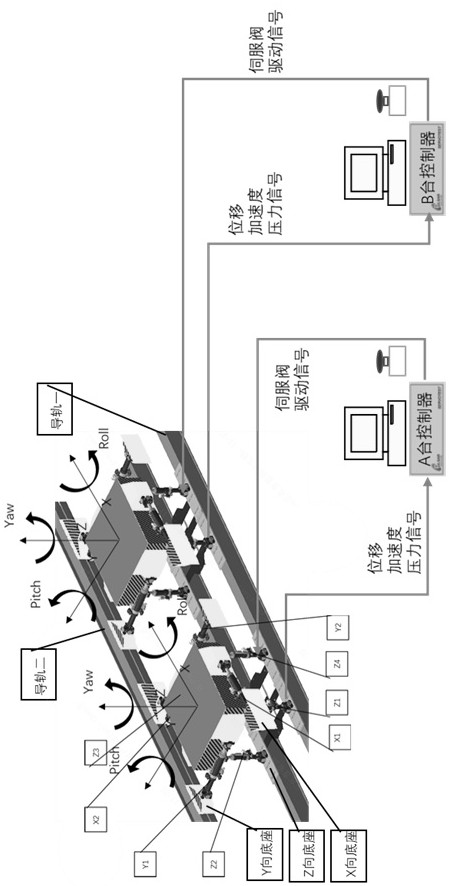
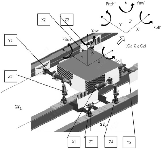
[0054] Such as figure 2 As shown, the electro-hydraulic servo-based dual-stage array system large-stiffness specimen test device includes two three-direction six-degree-of-freedom vibration tables, and the A-table control unit used to control the movement of the first three-direction six-degree-of-freedom vibration table. A device, a B-table controller used to control the movement of the second three-way six-degree-of-freedom vibration table, the three-way six-degree-of-freedom vibration table includes a vibration table surface, an X-direction base, and is installed between the vibration table surface and the X-direction base. The X-direction actuator used to load the X-direction of the vibrating table, the Y-direction base, the Y-direction actuator installed between the vibrating table and the Y-direction base and used to load the Y-direction of the vibrating table, Z The Z-direction actuator installed between the vibrating table surface and the Z-direction base and used to ...
Embodiment 2
[0060] When two three-direction six-degree-of-freedom vibrating tables work alone, no rigid specimen is installed between the two vibrating tables, and the controllers of A and B work independently without communication.
[0061] Such as Figure 2-4 As shown, there is no connection between the two three-direction six-degree-of-freedom vibration tables, and each vibration table is controlled by its own A controller or B controller without affecting each other. Figure 4 The command signal of station A is corresponding to the three-direction six-degree-of-freedom vibration table of A station. Two three-direction six-degree-of-freedom vibration tables. Figure 4 The drive signal A, servo valve A, actuator A, table A (the table of A three-way six-degree-of-freedom vibration table), acceleration signal A, displacement signal A, and pressure signal A are all matched with A three-way six-degree-of-freedom vibration table. degrees of freedom shaker. Similarly, drive signal B, servo v...
Embodiment 3
[0067] Such as Figure 5 , 6 As shown, when two three-direction six-degree-of-freedom vibrating tables work as an array, a rigid specimen is fixed between the two vibrating tables, and the controllers of A and B communicate through real-time shared memory cards. ; The calculation information is obtained by real-time calculation of the displacement signal, pressure signal, and acceleration signal to obtain the corresponding position, thrust signal, and acceleration information of the vibrating table; the command signal of the table array is input by the A controller and synchronously output to B At the same time, the two three-direction six-degree-of-freedom vibration tables send the thrust signals of each degree of freedom to each other in real time. The additional internal forces exerted on the specimen by the two three-direction six-degree-of-freedom vibration tables are obtained after the signals are differentiated. In order to eliminate the internal force, it is processe...
PUM
 Abstract
Description
Claims
Application Information
 - R&D
- Intellectual Property
- Life Sciences
- Materials
- Tech Scout
- Unparalleled Data Quality
- Higher Quality Content
- 60% Fewer Hallucinations
Browse by: Latest US Patents, China's latest patents, Technical Efficacy Thesaurus, Application Domain, Technology Topic, Popular Technical Reports.
© 2025 PatSnap. All rights reserved.Legal|Privacy policy|Modern Slavery Act Transparency Statement|Sitemap|About US| Contact US: help@patsnap.com


