Carbon fiber reinforced composite material preparation machine

A reinforced composite material and preparation machine technology, which is applied in the field of fiber and composite material preparation, can solve problems such as increased resistance, resin shedding and cracking, and reduced production speed of composite materials

Inactive Publication Date: 2021-08-31
蔡清洪
View PDF0 Cites 0 Cited by
  • Summary
  • Abstract
  • Description
  • Claims
  • Application Information

AI Technical Summary

Problems solved by technology

[0002] Composite materials refer to materials that are physically or chemically combined by two or more materials with different properties. Carbon fiber reinforced composite materials made of carbon fiber and resin have good tensile strength and corrosion resistance. In the prior art, the prepreg is molded, but during the molding process, the mold will heat the carbon fiber composite material to speed up the fusion of the resin and the carbon fiber. Since the resin will be liquefied after heating, the liquefied r

Method used


Image

  • Carbon fiber reinforced composite material preparation machine
  • Carbon fiber reinforced composite material preparation machine
  • Carbon fiber reinforced composite material preparation machine

Examples


Embodiment 1

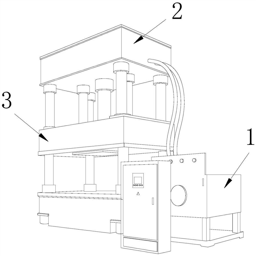
[0028] as attached figure 1 to attach Image 6 Shown:

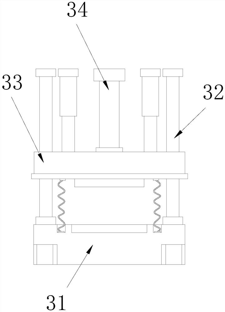
[0029] The invention provides a carbon fiber reinforced composite material preparation machine, the structure of which includes a controller 1, a hydraulic press 2, and a die 3. The left end of the controller 1 is embedded and connected to the right side of the hydraulic press 2, and the upper end of the die 3 is connected to the hydraulic press 2. The lower side is embedded and connected. The press mold 3 includes a bottom mold 31, a guide column 32, a pressing device 33, and a hydraulic rod 34. The outer end of the bottom mold 31 is movably engaged with the outside of the guide column 32. The guide column 32 The outer side is movably engaged with the outer end of the pressing device 33 , and the lower side of the hydraulic rod 34 is welded to the upper side of the middle part of the pressing device 33 .

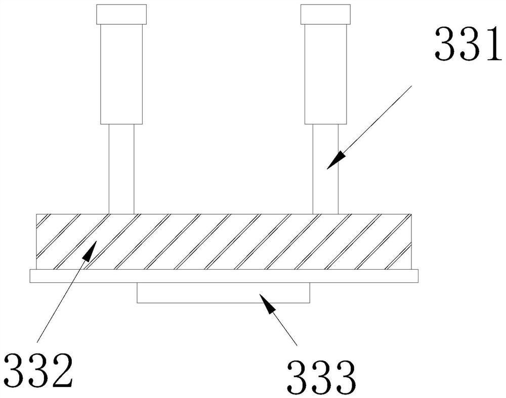
[0030] Wherein, the pressing device 33 includes a push rod 331, a die 332, and a protruding block 333, the lower s...

Embodiment 2

[0037] as attached Figure 7 to attach Figure 9 Shown:

[0038]Wherein, the bottom mold 31 includes a support base 311, a tension spring 312, and a female mold 313. The inner side of the support base 311 is embedded and connected with the outer side of the female mold 313. connected, the number of the tension springs 312 is two, and they are symmetrically distributed around the master mold 313, so that the tension springs 312 can pull up the master mold 313, which is beneficial to separate the bottom of the carbon fiber composite material from the master mold 313 open.

[0039] Wherein, the female mold 313 includes a fixed block 13a, a filter plate 13b, and an ejector block 13c. Outer clearance fits, and described filter plate 13b is vertically installed with fixed block 13a, and the diameter of the upper end of described ejector block 13c is less than the internal diameter of fixed block 13a bottom, makes ejector block 13c move upwards and the air of upper end is extruded...


PUM


Abstract

The invention discloses a carbon fiber reinforced composite material preparation machine which structurally comprises a controller, a hydraulic machine and a pressing die, the left end of the controller is fixedly connected with the right side of the hydraulic machine in an embedded mode, the upper end of the pressing die is fixedly connected with the lower side of the hydraulic machine in an embedded mode, an ejector rod can move downwards to eject a separator in a stamping die downwards, then a shrinking machine is started for shrinking, a supporting plate can enter a gap between a carbon fiber composite plate and a mold to separate the carbon fiber composite material from a protruding block fixed to a lower cushion block of the mold, the separation process is accelerated, the material taking speed after the completion of preparation is increased, the production efficiency is improved, a tension spring pulls an ejection block to move upwards, air in the female die is ejected out upwards in a moving process, the carbon fiber composite material attached to the upper side of a plate body is pushed out, the carbon fiber composite material attached to the outer side of a filter plate can be uniformly separated from the filter plate, resin at the outer side of the carbon fiber composite material is prevented from falling off and cracking, and the qualified rate of the carbon fiber composite material is improved.

Description

technical field [0001] The invention belongs to the field of fiber and composite material preparation, and more specifically relates to a carbon fiber reinforced composite material preparation machine. Background technique [0002] Composite materials refer to materials that are physically or chemically combined by two or more materials with different properties. Carbon fiber reinforced composite materials made of carbon fiber and resin have good tensile strength and corrosion resistance. In the prior art, the prepreg is molded, but during the molding process, the mold will heat the carbon fiber composite material to speed up the fusion of the resin and the carbon fiber. Since the resin will be liquefied after heating, the liquefied resin and the surface of the mold are fully Fitting, the resin solidified after the composite material is cooled will adhere to the surface of the mold, resulting in increased resistance when taking out the material, reducing the production speed...

Claims


Application Information

Patent Timeline
IPC IPC(8): B29C70/34B29C70/54B29C33/44
CPCB29C33/44B29C70/34B29C70/54
Inventor 蔡清洪
Owner 蔡清洪
Why Eureka
Try Eureka