Column base joint with additional grid type damper capable of being replaced after earthquake

A technology of column foot joints and dampers, which is applied in the field of anti-seismic structural engineering, can solve problems such as difficult maintenance after earthquakes, and achieve the effects of improving anti-seismic performance, easy replacement, and clear force transmission

Inactive Publication Date: 2021-08-31
CHONGQING UNIV
View PDF10 Cites 2 Cited by
  • Summary
  • Abstract
  • Description
  • Claims
  • Application Information

AI Technical Summary

Problems solved by technology

[0004] In view of this, the purpose of the present invention is to provide a post-seismic post-seismic replaceable grid-type damper column foot joint to solve the problem of post-earthquake maintenance difficulties in the existing concrete frame structure column foot joints

Method used


Image

  • Column base joint with additional grid type damper capable of being replaced after earthquake
  • Column base joint with additional grid type damper capable of being replaced after earthquake
  • Column base joint with additional grid type damper capable of being replaced after earthquake

Examples


Embodiment 1

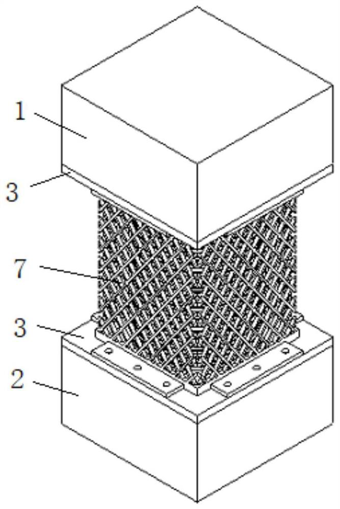
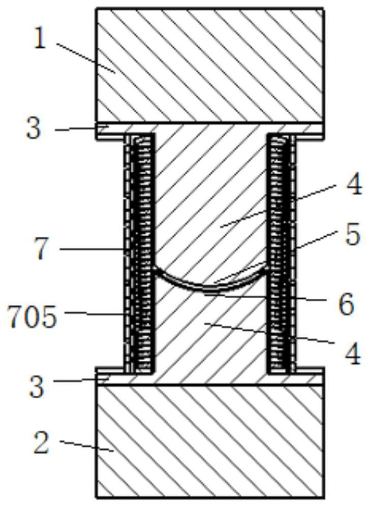
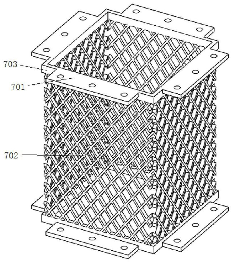
[0034] see Figure 1 to Figure 4 , is a post-seismic replaceable grid-type damper 7 column base node, including the upper column 1 and the lower column 2, which are located in the axial center of the upper column 1 and the lower column 2 and are opposite to each other. The bowl-shaped support 4, and the grid-type damper 7 surrounding the bowl-shaped support 4.

[0035] Specifically, the upper column 1 and the lower column 2 are reinforced concrete square columns, and steel end plates 3 are respectively fixed on the cylindrical surfaces facing each other, and the centers of the two steel end plates 3 are respectively connected to steel bowl-shaped supports 4. Among them, the end surface of the bowl-shaped support 4 of the upper column 1 has an arc-shaped protrusion 5, and the end surface of the bowl-shaped support 4 of the lower column 2 has an arc-shaped groove 6, an arc-shaped protrusion 5 and an arc-shaped groove 6 to form a convex-concave arc-shaped matching structure. Th...

Embodiment 2

[0042] Such as Figure 5 As shown, the main difference between Embodiment 2 and Embodiment 1 is that the outer circumference of the bowl-shaped support 4 of the upper column 1 and the lower column 2 is covered with a plurality of disc springs 705, and the disc springs 705 are located inside the grid-type damper 7 . Utilizing the elastic force of the disc spring 705, it cooperates with the grid-type damper 7 to play the effect of shock absorption and energy dissipation, further improving the seismic performance of the column foot joint.

[0043]In addition, the 703 and the wave spring 704 in the first embodiment can also be used in combination with the disc spring 705 in the second embodiment, so as to better improve the anti-vibration performance.


PUM


Abstract

The invention relates to a column base joint with an additional grid type damper capable of being replaced after an earthquake, and belongs to the technical field of structural engineering earthquake resistance. The column base joint with the additional grid type damper capable of being replaced after the earthquake comprises an upper column, a lower column, a bowl-shaped support positioned in an axial center of the upper column and the lower column and the grid type damper arranged around the bowl-shaped support. The end faces of an upper bowl-shaped support and a lower bowl-shaped support are provided with arc-shaped protrusions and arc-shaped grooves respectively, and a plurality of wave springs are additionally arranged between the arc-shaped protrusions and the arc-shaped grooves, or the peripheries of the bowl-shaped supports are sleeved with a plurality of disc springs. The grid type damper is a steel structural part and comprises frames and grids interwoven in the frames, and an upper frame and a lower frame are detachably connected with steel end plates of the upper column and the lower column respectively. According to the column base joint with the additional grid type damper capable of being replaced after the earthquake, force transmission is clear, the bowl-shaped support can bear axial force and shearing force, and rotation in all directions can be achieved during the earthquake. The grid type damper can dissipate earthquake energy, improves anti-seismic capacity, and is convenient to replace and maintain after the earthquake.

Description

technical field [0001] The invention belongs to the field of anti-seismic technology of structural engineering, and relates to a column base node of a grid type damper which can be replaced after an additional earthquake. Background technique [0002] At present, performance-based seismic design has become the mainstream of seismic design. How to make the whole building, even the whole city and even the whole society recover after an earthquake has attracted close attention and extensive discussions in the field of earthquake engineering in recent years. How to design a structure that does not cause damage or can only be quickly repaired in an earthquake will become one of the important research directions for sustainable development of engineering earthquake resistance. By "weakening" certain parts of the structural system and realizing concentrated energy dissipation in these parts, the damage of the structure under the action of the earthquake can be effectively controlle...

Claims


Application Information

Patent Timeline
Patent Type & Authority Applications(China)
IPC IPC(8): E04H9/02E04B1/98
CPCE04H9/021E04H9/025E04B1/98
Inventor 白久林贺晶陈辉明金双双杨经纬胡少伟
Owner CHONGQING UNIV
Why Eureka
Try Eureka