Expansion type rotatable drilling liner hanger

A liner hanger and expansion technology, which is applied in the direction of wellbore/well components, earthwork drilling, sealing/packing, etc., can solve the problems of small contact area, poor liner stability effect, and affect the use of liner, etc. Achieve the effects of not easy to settle and stratify, good cementing effect, and save resources

Inactive Publication Date: 2021-08-31
任丘市华北石油华坤钻采机械有限公司
View PDF0 Cites 0 Cited by
  • Summary
  • Abstract
  • Description
  • Claims
  • Application Information

AI Technical Summary

Problems solved by technology

[0004] However, the tight part between the slips on the liner hanger used in the above cementing operation and the inner wall of the deep well is only one end of the slips, the contact area between the two is small, and the stability effect of the liner in the deep well Poor, and because the pressure in the tailpipe is easily affected by the underground direction of the deep well, it is easy to cause the pressure in the tailpipe to be unstable, make the slips retract, cause the seat to hang, and the reliability is poor, and it is also easy to When the pressure in the liner tube does not reach the expected pressure, the slips will move relative to the liner tube, resulting in early settling, and when the cementing fluid is injected into the liner tube through the pipeline system, the deep well is deep and the pipeline system is long , the long-term flow of cementing slurry is likely to cause sedimentation and reduce the cementing effect. At the same time, the cementing slurry is easy to adhere to the liner, resulting in waste of cementing slurry, and it is easy to affect the use of the liner

Method used


Image

  • Expansion type rotatable drilling liner hanger
  • Expansion type rotatable drilling liner hanger
  • Expansion type rotatable drilling liner hanger

Examples


Embodiment

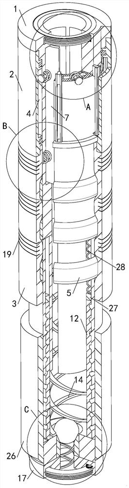
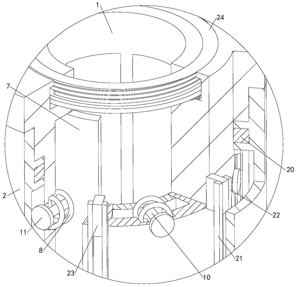
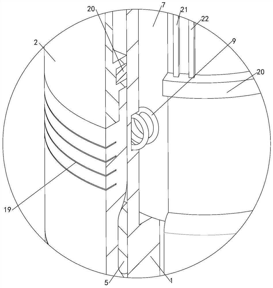
[0032] see Figure 1-6, an expandable rotatable liner hanger, comprising a liner 1 and a hydraulic cylinder mount mechanism 2, and also includes an elastic slip pipe 3, the hydraulic cylinder mount mechanism 2 is installed on the tail pipe 1, and the hydraulic cylinder mount mechanism A plurality of first guide strips 21 and a plurality of second guide strips 22 are fixedly connected to the inner wall of the tail pipe 2, and a plurality of guide blocks 23 are fixedly connected to the outer wall of the tail pipe 1, and the first guide strips 21 and the second guide strips 22 are respectively The two ends of the guide block 23 are slidably fitted, so that the directionality of the hydraulic cylinder mounting mechanism 2 relative to the tail pipe 1 is better, which is more practical. Two concave ring grooves are provided in the hydraulic cylinder mounting mechanism 2, and the two A seal ring 20 is arranged in each concave ring groove, and the inner wall of the seal ring 20 is sli...


PUM


Abstract

The invention relates to the technical field of drilling liner hangers, in particular to an expansion type rotatable drilling liner hanger. The expansion type rotatable drilling liner hanger comprises a drilling liner, a hydraulic cylinder seat hanging mechanism and an elastic slip pipe. The hydraulic cylinder seat hanging mechanism is installed on the drilling liner, and the hydraulic cylinder seat hanging mechanism and the drilling liner are matched to form a hydraulic driving cavity; a plurality of annular slot sets are formed in the elastic slip pipe, and the elastic slip pipe is arranged on the drilling liner in a matched mode; the drilling liner is connected with a plurality of expansion rings, a storage ring groove is formed in the elastic slip pipe, a plurality of liquid passing holes are formed in the drilling liner, and the multiple liquid passing holes communicate with the hydraulic driving cavity; and a plurality of pressure maintaining assemblies are installed in the drilling liner, an annular groove is formed in the drilling liner, a scraper assembly is installed in the annular groove, a spiral stirring assembly is installed in the scraper assembly, and a pressure building ball is arranged in the spiral stirring assembly. The stabilizing effect of the drilling liner in a deep well is good, using is reliable, advanced hanging is not prone to being caused, in the process that well cementation slurry is injected into the drilling liner, precipitation and layering are not prone to happening, and resources are saved.

Description

technical field [0001] The invention relates to the technical field of liner hangers, in particular to an expandable rotatable liner hanger. Background technique [0002] As we all know, liner cementing is one of the commonly used methods in the process of deep well cementing. Fixed suspension, one of the auxiliary devices for better cementing. [0003] The existing stern tube hanger includes a stern tube and slips. The slips are arranged on the stern tube, and a protruding ring matching the slips is fixedly connected to the stern tube. The slips and the protruding ring are in contact with each other. A hydraulic cylinder hanger mechanism for slips driving is installed, and a pressure transmission hole for driving the hydraulic cylinder hanger mechanism is opened on the stern pipe. When in use, the expandable rotatable tailpipe hanger is first matched with the pipeline system Go down into the deep well, pressurize and inject well flushing fluid into the pipeline system, an...

Claims


Application Information

Patent Timeline
IPC IPC(8): E21B23/01E21B33/13
CPCE21B23/01E21B33/13
Inventor 方坤贤
Owner 任丘市华北石油华坤钻采机械有限公司
Why Eureka
Try Eureka