Primary support structure and method for controlling surrounding rock deformation through preexpansive force

A technology of surrounding rock deformation and initial support, applied in earth-moving drilling, shaft equipment, wellbore lining, etc., can solve problems such as breaking the stress balance state, and achieve the effect of suppressing creep, ensuring long-term safety, and being able to withstand bending moments.

Active Publication Date: 2021-08-31
JINAN MUNICIPAL ENG DESIGN & RES INSITITUTE GRP
View PDF7 Cites 0 Cited by
  • Summary
  • Abstract
  • Description
  • Claims
  • Application Information

AI Technical Summary

Problems solved by technology

[0003] The inventors learned that after the excavation of the tunnel chamber in weak ground, the stress of the surrounding rock is released, resulting in the break of the original stress balance state

Method used


Image

  • Primary support structure and method for controlling surrounding rock deformation through preexpansive force
  • Primary support structure and method for controlling surrounding rock deformation through preexpansive force
  • Primary support structure and method for controlling surrounding rock deformation through preexpansive force

Examples


Embodiment 1

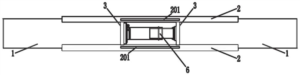
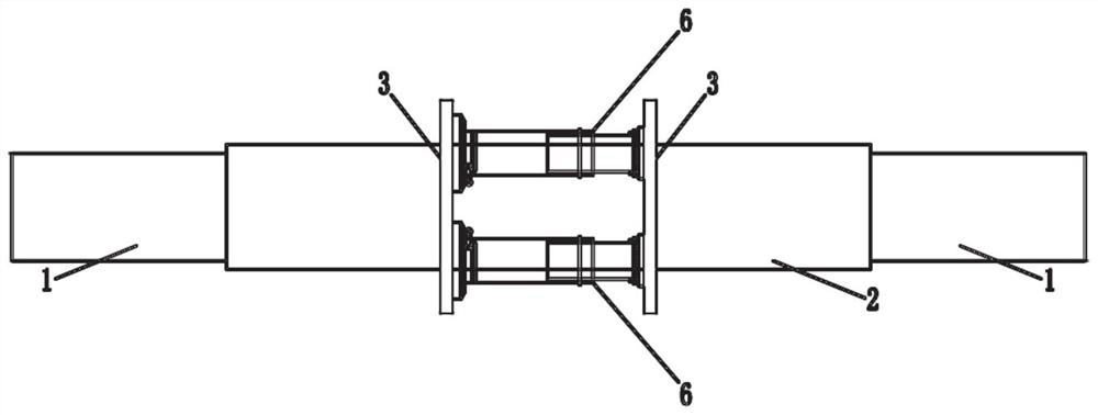
[0032] like Figure 1-Figure 5 As shown in Fig. 1 , a primary support structure for the pre-expansion force to control the deformation of the surrounding rock is given, including the top section steel, the two ends of the top section steel are respectively connected with the side section steel, and the top section steel and the side section steel are combined into an arch steel The lower end of the side section steel is connected to the arch feet, and an inversion is set between the two arch feet. The sleeve is connected, and the side wall of the sleeve is provided with a gap, which is used to take and place the jack into the inner cavity of the sleeve; the inner cavity of the sleeve can place a support plate through the gap, and the support plate can fill the space after the jack is taken out, and the support plate can be connected with the sleeve The cylinder is fixed to maintain the prestress of the arch steel frame, arch feet and inverted arches on the surrounding rock.

...

Embodiment 2

[0041] This embodiment provides a primary support method for controlling the deformation of the surrounding rock by the pre-expansion force. The primary support structure for controlling the deformation of the surrounding rock by using the pre-expansion force described in Example 1 includes the following steps:

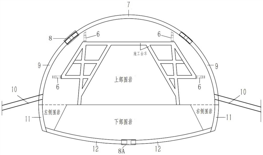
[0042] Excavate the surrounding rock of the upper part of the tunnel, assemble the top section steel 7, the sleeve 2 and the inverted arch section steel 12 to form an arched steel frame;

[0043] The arched steel frame is lifted by the construction trolley until the outer wall surface is in contact with the inner wall of the tunnel, and the jack 6 is lifted up, so that under the set jacking pressure, the end surface distance between the top section steel 7 and the side section steel 9 is enlarged to the maximum value;

[0044] Fix the top section steel 7, the side section steel 9 and the sleeve 2, and fix the lower part of the side section steel 9 to the side wall of t...


PUM


Abstract

The invention relates to a primary support structure and method for controlling surrounding rock deformation through preexpansive force. The structure comprises top profile steel, the two ends of the top profile steel are connected with side profile steel correspondingly, and the top profile steel and the side profile steel are combined to form an arched steel frame; the top profile steel is connected with the side profile steel through a sleeve, a notch is formed in the side wall of the sleeve and used for taking and placing a jack out of and into an inner cavity of the sleeve, and the jack can adjust the distance between the top profile steel and the side profile steel to apply prestress to surrounding rock; and a supporting plate can be placed in the inner cavity of the sleeve through the notch, the supporting plate can fill the space after the jack is taken out, and the supporting plate can be fixed to the sleeve, the side profile steel and the top profile steel so as to keep the prestress of the arched frame to surrounding rock. According to the structure and method, the prestress can be applied to the tunnel surrounding rock during primary supporting, so that wriggling of the tunnel after primary supporting is reduced.

Description

technical field [0001] The disclosure belongs to the technical field of tunnel construction, and in particular relates to an initial support structure for controlling deformation of surrounding rock by pre-expansion force. Background technique [0002] The statements herein merely provide background information related to the present disclosure and do not necessarily constitute prior art. [0003] The inventors have learned that after the excavation of the tunnel chamber in weak ground, the stress of the surrounding rock is released, resulting in the break of the original stress balance state. Before the primary support is closed into a ring, the deformation of the surrounding rock is mainly elastic-plastic deformation. After the initial support and secondary lining construction of the tunnel is completed, the deformation of the surrounding rock is mainly creep deformation, which can last for several years or even decades. With the further development of creep, it will caus...

Claims


Application Information

Patent Timeline
Patent Type & Authority Applications(China)
IPC IPC(8): E21D11/14E21D11/18E21D11/10
CPCE21D11/14E21D11/18E21D11/105
Inventor 郑召怡李彦明毛化冰彭小刚王云博张锐张光利
Owner JINAN MUNICIPAL ENG DESIGN & RES INSITITUTE GRP
Why Eureka
Try Eureka