
Pressure gauge and rapid calibration method and pressure calibration device thereof

A pressure gauge and fast technology, applied in the direction of measuring devices, measuring fluid pressure, instruments, etc., can solve the problems of leakage of working medium, residue, and manufacturing consistent sealing means can not achieve the sealing effect, so as to improve work efficiency and reduce gas pressure. The effect of reducing the risk of road leakage, ensuring sealing and working continuity

Pending Publication Date: 2021-08-31
BEIJING CONST INSTR TECH INC
View PDF0 Cites 0 Cited by
  • Summary
  • Abstract
  • Description
  • Claims
  • Application Information

AI Technical Summary

Problems solved by technology

[0008] Whether it is a three-way ball valve or other types of valve structure, there will inevitably be leakage problems and risks, because as long as it is a valve, its sealing means will be greatly restricted (because the valve must be opened), and the manufacturing consistency Various factors such as wear and tear will cause the limited sealing method to fail to achieve the desired sealing effect. Therefore, in many application scenarios, such valve-type methods are not allowed on the working pipeline or pressure gauge;
[0009] In addition, if the medium used in the working pipeline is a special medium, then the pressure gauge of the above-mentioned prior art improvement scheme also needs to use this special medium when calibrating, and it is also necessary to solve the residual or external pressure during the pipeline switching process. Disposal of leaked working medium, especially when the working medium is poisonous or hazardous

Method used


Image

  • Pressure gauge and rapid calibration method and pressure calibration device thereof
  • Pressure gauge and rapid calibration method and pressure calibration device thereof
  • Pressure gauge and rapid calibration method and pressure calibration device thereof

Examples


specific Embodiment 1

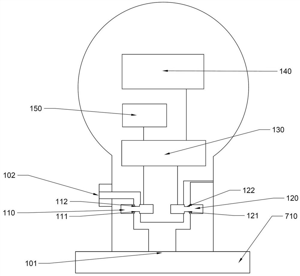
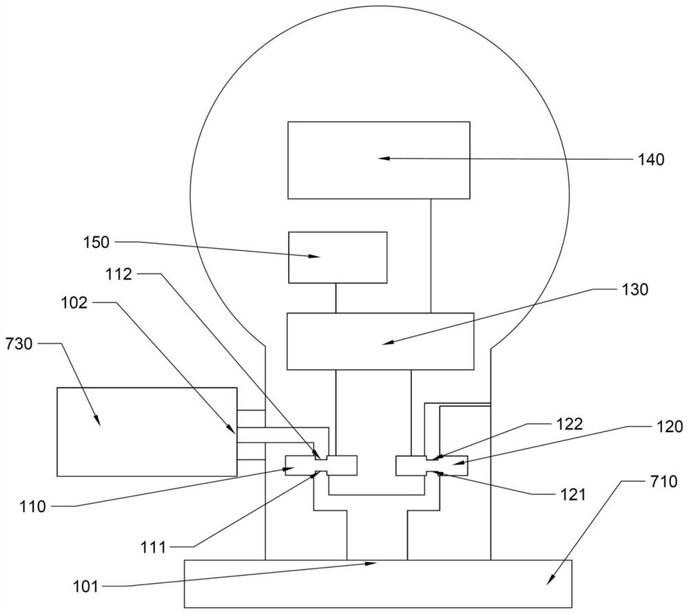
[0056] example, such as figure 2 as well as image 3 As shown, a pressure gauge includes a first pressure sensor 110 , a second pressure sensor 120 , a working pressure port 101 and a quick calibration pressure port 102 .

[0057] The first pressure sensor 110 includes a first pressure-sensing surface 111 and a second pressure-sensing surface 112, the first pressure sensor measures the relative pressure of the first pressure-sensing surface and the second pressure-sensing surface and generates a pressure signal;

[0058] The second pressure sensor 120 includes a first pressure-sensing surface 121 and a second pressure-sensing surface 122, the second pressure sensor measures the relative pressure of the first pressure-sensing surface and the second pressure-sensing surface and generates a pressure signal;

[0059] The working pressure interface 101 is used to communicate with the measured pressure source, so that the first pressure sensor and the second pressure sensor can me...

specific Embodiment 2

[0110] example, such as Figure 6 As shown, the pressure gauge includes a gauge head 303 and a pressure acquisition module 304;

[0111] The front of the meter head 303 is provided with a display screen 340 for displaying pressure value information. The inside of the meter head 303 is provided with a processing module 330 for information processing. The fixed structure 305 and the signal connection part 306, the fixed structure is used to fix the meter head and the pressure acquisition module, the signal connection part is used to establish a signal connection with the pressure acquisition module, and the processing module 330 is respectively connected to the signal connection part 306 and the pressure acquisition module of the meter head. Display screen 340 signal connection.

[0112] The lower end surface of the pressure acquisition module 304 is provided with a working pressure port 301, and when a pressure gauge is used for pressure measurement, the working pressure port ...

specific Embodiment 3

[0200] example, such as Figure 10 and Figure 11 As shown, the pressure gauge includes a casing, a display screen 440 is arranged on the front of the casing, a working pressure port 401 is arranged on the bottom of the casing, and a quick calibration pressure port 402 is arranged on the lower part of the back of the casing.

[0201] The pressure sensor 410 is fixed inside the housing and includes a first pressure-sensing surface 411 and a second pressure-sensing surface 412. The first pressure-sensing surface 411 communicates with the working pressure interface 401, and the second pressure-sensing surface 412 communicates with the quick calibration pressure interface. 402 is connected, and the pressure sensor 410 measures the relative pressure of the first pressure-sensing surface and the second pressure-sensing surface, and generates a pressure signal (analog electrical signal) indicating the relative pressure value.

[0202] What is connected with the pressure sensor signa...


PUM


Abstract

The invention provides a pressure gauge and a rapid calibration method and a pressure calibration device thereof. The pressure gauge comprises a first pressure sensor, a second pressure sensor, a working pressure interface and a rapid calibration pressure interface, wherein the first pressure sensing surface of the first pressure sensor and the first pressure sensing surface of the second pressure sensor are communicated with the working pressure interface, the second pressure sensing surface of the first sensor is communicated with the quick calibration pressure interface, the second pressure sensing surface of the second sensor is communicated with the atmosphere, and in a quick calibration mode, the working pressure interface is communicated with a measured pressure source, the quick calibration pressure interface is communicated with a calibration pressure source; the first pressure sensor measures the relative pressure of the measured pressure source and the calibration pressure source, and the second pressure sensor measures the measured pressure. According to the invention, the calibration of the pressure gauge can be realized under the condition that the pressure gauge and the measured pressure source are continuously communicated, and the sealing performance and the working continuity of a gas circuit of the measured pressure source are ensured to the greatest extent.

Description

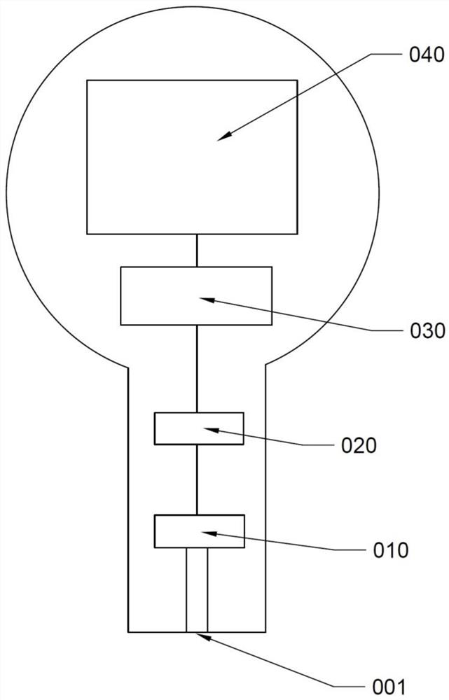
technical field [0001] The invention relates to the technical field of pressure measurement and calibration, in particular to a pressure gauge capable of quick calibration without disassembly and assembly, a quick calibration method for the pressure gauge, and a pressure gauge for calibrating the pressure gauge. Calibration device. Background technique [0002] A pressure gauge is an industrial instrument used to measure pressure, such as figure 1 As shown, the pressure gauge in the prior art includes a pressure sensor 010, an analog-to-digital conversion unit 020, a data processing unit 030, and a display unit 040. The lower end of the pressure gauge is provided with a pressure measuring port 001. The port 001 is connected, so that the working medium with load pressure is transmitted to the pressure sensor through the pressure measuring port. The pressure sensor 010 generates an analog electrical signal representing the pressure value based on the pressure on its pressure-...

Claims


Application Information

Patent Timeline
Patent Type & Authority Applications(China)
IPC IPC(8): G01L11/00G01L27/00
CPCG01L11/00G01L27/002G01L27/005
Inventor 姜维利
Owner BEIJING CONST INSTR TECH INC
Learn More