Imaging lens, camera module and electronic device

An imaging lens, imaging lens technology, applied in TV, installation, electrical components, etc., can solve problems such as insufficient roundness, insufficient overall structural strength, and poor melt flow rate.

Active Publication Date: 2021-08-31
LARGAN PRECISION
View PDF6 Cites 0 Cited by
  • Summary
  • Abstract
  • Description
  • Claims
  • Application Information

AI Technical Summary

Problems solved by technology

However, during the injection molding process of the plastic lens barrel, the melt flow rate of the injected plastic may be poor and the degree of molding pressure may be insufficient due to factors in the manufacturing environment. There are problems of insufficient roundness and insufficient flatness on the side of the object or image, and the problems of insufficient coaxiality of core assembly and insufficient strength of the overall structure are also prone to occur.

Method used


Image

  • Imaging lens, camera module and electronic device
  • Imaging lens, camera module and electronic device
  • Imaging lens, camera module and electronic device

Examples


no. 1 example

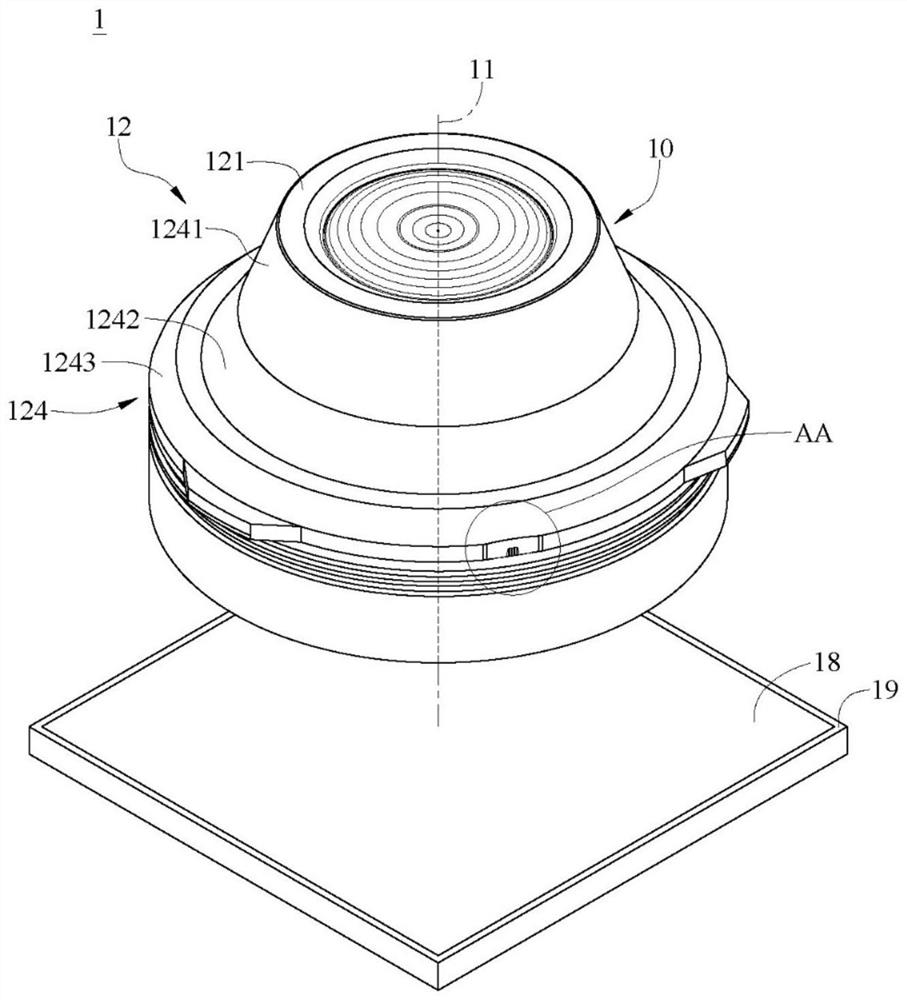
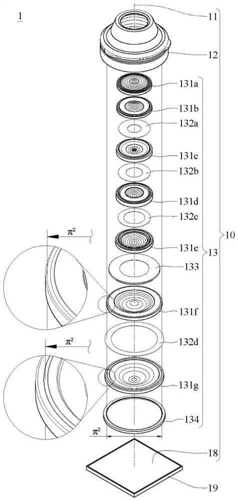
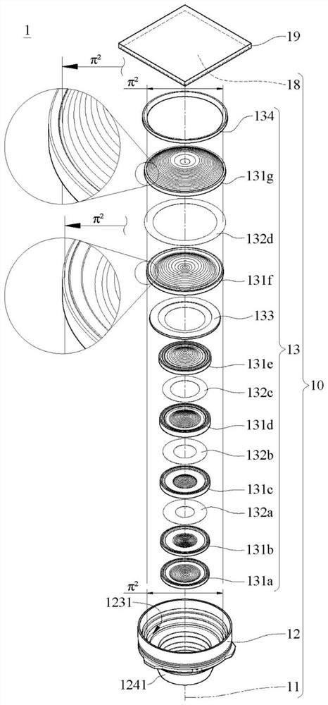
[0117] Please refer to Figure 1 to Figure 10 ,in figure 1 A perspective view showing a camera module according to a first embodiment of the present invention, figure 2 draw figure 1 An exploded schematic diagram of the camera module, image 3 draw figure 1 Another exploded schematic diagram of the camera module, Figure 4 draw figure 1 A partially enlarged schematic diagram of the AA area of ​​the camera module, Figure 5 draw figure 1 The top view diagram of the camera module, Figure 6 draw figure 1 Schematic side view cutaway of the camera module, Figure 7 draw Figure 6 An exploded schematic diagram of the camera module, Figure 8 Shown formed in an injection molding mold figure 1 A schematic diagram of the plastic lens barrel of the camera module, Figure 9 depicting injection molded figure 1 The three-dimensional schematic diagram of the plastic flow direction of the plastic lens barrel of the camera module in the forming process, Figure 10 draw Figu...

no. 2 example

[0134] Please refer to Figure 11 to Figure 17 ,in Figure 11 A schematic perspective view of a camera module according to a second embodiment of the present invention is shown, Figure 12 draw Figure 11 A partially enlarged schematic diagram of the BB area of ​​the camera module, Figure 13 draw Figure 11 The top view diagram of the camera module, Figure 14 draw Figure 11 Schematic side view cutaway of the camera module, Figure 15 draw Figure 14 An exploded schematic diagram of the camera module, Figure 16 depicting injection molded Figure 11 The three-dimensional schematic diagram of the plastic flow direction of the plastic lens barrel of the camera module in the forming process, Figure 17 draw Figure 16 The cross-sectional schematic diagram of the plastic flow direction of the plastic lens barrel in the forming process. In the following, only the differences between the second embodiment of the present invention and the foregoing embodiments will be de...

no. 3 example

[0151] Please refer to Figure 18 to Figure 24 ,in Figure 18 A schematic perspective view of a camera module according to a third embodiment of the present invention is shown, Figure 19 draw Figure 18 A partially enlarged schematic diagram of the CC area of ​​the camera module, Figure 20 draw Figure 18 The top view diagram of the camera module, Figure 21 draw Figure 18 Schematic side view cutaway of the camera module, Figure 22 draw Figure 21 An exploded schematic diagram of the camera module, Figure 23 depicting injection molded Figure 18 The three-dimensional schematic diagram of the plastic flow direction of the plastic lens barrel of the camera module in the forming process, Figure 24 draw Figure 23 The cross-sectional schematic diagram of the plastic flow direction of the plastic lens barrel in the forming process. Only the differences between the third embodiment of the present invention and the foregoing embodiments will be described below, and o...


PUM


Abstract

The utility model provides an imaging lens, which is provided with an optical axis and comprises a plastic lens cone and an imaging lens group. Plastic lens barrel surrounding optical axis. The plastic lens barrel includes an object-side surface, an image-side surface, an inner peripheral portion, and an outer peripheral portion. The object-side surface and the image-side surface are disposed opposite to each other and are substantially perpendicular to the optical axis. The inner peripheral portion and the outer peripheral portion connect the object side surface and the image side surface, and the outer peripheral portion is farther from the optical axis than the inner peripheral portion. The inner peripheral part is provided with a parallel inner edge surface, and the outer peripheral part is provided with a first outer peripheral surface and an injection mark. The imaging lens group is arranged in the plastic lens barrel. The imaging lens group includes a plurality of imaging lens elements. The outer diameter of at least one imaging lens element is larger than [pi]2 mm. The outer edge of at least one imaging lens element is in solid contact with the parallel inner edge surface of the inner peripheral part. The first outer peripheral surface, the material injection mark and the parallel inner edge surface are sequentially arranged from the object side to the image side. The first outer peripheral surface tapers toward the object-side surface. The present invention also provides a camera module with the imaging lens and an electronic device with the camera module.

Description

technical field [0001] The present invention relates to an imaging lens, a camera module and an electronic device, in particular to an imaging lens and a camera module suitable for the electronic device. Background technique [0002] With the improvement of semiconductor process technology, the performance of electronic photosensitive elements has been improved, and the pixels can reach a smaller size. Therefore, optical lenses with high imaging quality have become an indispensable part. In addition, with the rapid development of technology, the application range of electronic devices equipped with optical lenses is wider, and the requirements for optical lenses are also more diverse. [0003] Well-known optical lenses usually include an injection-molded plastic lens barrel, which not only reduces production costs, but also increases the degree of freedom in the design of the inner wall of the lens barrel to meet diverse needs. However, during the injection molding process ...

Claims


Application Information

Patent Timeline
Patent Type & Authority Applications(China)
IPC IPC(8): G02B7/02
CPCG02B7/021G03B17/12G03B30/00G02B7/022G02B13/0045G02B13/002H04N23/55
Inventor 张临安周明达
Owner LARGAN PRECISION
Why Eureka
Try Eureka