
Photoelectric film position adjusting device

A technology for adjusting devices and photoelectric thin films, applied in optics, nonlinear optics, instruments, etc., can solve the problems of slow manpower adjustment, no stable customer resources, insufficient capital scale, etc.

Active Publication Date: 2021-08-31
九江力达科技股份有限公司
View PDF9 Cites 0 Cited by
  • Summary
  • Abstract
  • Description
  • Claims
  • Application Information

AI Technical Summary

Problems solved by technology

After the survival of the fittest in the industry, those small companies that cannot guarantee product quality, have insufficient capital scale, have no stable customer resources, and have a single production location are gradually eliminated in the competition
[0005] In the pasting process of the diaphragm, before the two diaphragms are pasted, they must be individually adjusted and positioned in the correct position, and then they can be aligned and bonded accurately and without deviation. In the past, most of them were adjusted manually, but This manual adjustment method is quite slow, and it cannot be aligned and fit, and the product yield is quite low

Method used


Image

  • Photoelectric film position adjusting device
  • Photoelectric film position adjusting device
  • Photoelectric film position adjusting device

Examples


Embodiment 1

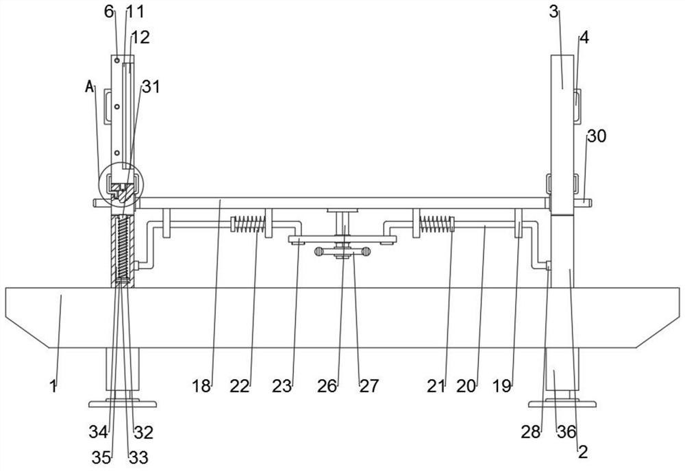
[0040] see Figure 1-5 , a photoelectric film position adjustment device, comprising a base 1 and bolts 10, a support plate 2 is fixed on the base 1, the support plate 2 is slidably connected to a connecting block 37, the connecting block 37 is slidably connected to a moving plate 3, and the connecting block 37 is fixed Connecting plate 5 is arranged, and moving plate 3 is corresponding with connecting plate 5 positions, and is provided with through hole 6 on moving plate 3, and is provided with through hole 6 on connecting plate 5, and the through hole 6 on moving plate 3 and connecting plate 5 offers The position is on the same horizontal line, the side walls of the moving plate 3 and the connecting plate 5 are provided with a fixed block 7, and a connecting rod 8 runs through between the fixed blocks 7, and the connecting rod 8 runs through the moving plate 3 and the connecting plate 5 through the through hole 6, and the moving plate 3 and the side close to the connection p...

Embodiment 2

[0042] see figure 1 and Figure 4 , the side wall of the connection block 37 is provided with handles 30, the handles 30 are evenly and symmetrically distributed on the side walls of the symmetrical connection block 37, and the handles 30 are used to lift the connection block 37 and move in the vertical direction so as to change the clamping photoelectric The height of the film is convenient for the staff to carry out the lamination operation. The side wall of the moving plate 3 is provided with grippers 4. The grippers 4 are evenly and symmetrically distributed on the side walls of the symmetrical moving plate 3. The grippers 4 are convenient for the moving plate 3 and the connecting plate 5. The auxiliary effect is played when the bolts 10 are close to each other.

Embodiment 3

[0044] see figure 1 and Figure 4 , the connecting rod 8 runs through the moving plate 3 and the connecting plate 5, the connecting rod 8 is covered with a spring 9, the spring 9 can make the moving plate 3 and the connecting plate 5 move closer to each other more stable, and also play a buffering effect To prevent excessive clamping force from damaging the photoelectric film, a gasket 12 is provided in the clamping groove 11. The gasket 12 has a good anti-skid effect and prevents the photoelectric film from sliding and changing its position after being clamped.


PUM


Abstract

A photoelectric film position adjusting device disclosed by the present invention comprises a base and a bolt, a supporting plate is fixed on the base and is in sliding connection with a connecting block, and the connecting block is in sliding connection with a moving plate. A connecting plate is fixed on the connecting block, a through hole is formed in the moving plate, and a through hole is formed in the connecting plate. The positions of the through holes in the movable plate and the connecting plate are located on a same horizontal line, and fixing blocks are arranged on the side walls of the movable plate and the connecting plate. According to the device, a photoelectric film is clamped by the moving plate and the connecting plate in a clamping groove, the effect is obviously improved compared with the traditional manual straightening, the ends at the two sides of the photoelectric film can be kept in a straightening state after being clamped in the clamping groove, the follow-up attachment is facilitated, manpower is reduced, the attachment efficiency is also greatly improved, and compared with a traditional mode, the standard reaching rate of an attached finished product is greatly improved.

Description

technical field [0001] The invention relates to the technical field of photoelectric thin film position adjustment devices, in particular to a photoelectric thin film position adjustment device. Background technique [0002] Photoelectric display thin film devices mainly include optical films and tapes for photoelectric display. According to their uses, they can also be subdivided into two types: adhesive products and insulating products. The application of optical film mainly includes reflective film, diffusion film, prism film, double prism film and integrated (or composite) optical film. [0003] Insulation products are generally made of PET, PVC, PC and other materials. These materials have insulating effect, and sometimes anti-static liquid is coated on the surface of the material to achieve anti-static effect, or in the process of material production. Anti-static particles are added to the particles to achieve anti-static effect. This type of product is generally use...

Claims


Application Information

Patent Timeline
Patent Type & Authority Applications(China)
IPC IPC(8): G02F1/13
CPCG02F1/1303
Inventor 彭凤军
Owner 九江力达科技股份有限公司
Learn More