Height-adjustable reconfigurable reflective array antenna structure and design method

A technology of reflect array antenna and design method, applied to antennas, electrical components, etc., can solve the problems of large loss, complex unit design, narrow antenna bandwidth, etc., and achieve the effect of reducing loss, reducing design cycle, and improving bandwidth

Inactive Publication Date: 2021-08-31
GUIZHOU UNIV
View PDF6 Cites 0 Cited by
  • Summary
  • Abstract
  • Description
  • Claims
  • Application Information

AI Technical Summary

Problems solved by technology

[0004] The technical problem to be solved by the present invention is to provide a height-adjustable reconfigurable reflectarray antenna structure and design method to solve the existing technology of reconfigurable reflectarray antenna with narrow bandwidth, large loss and complicated unit design. question

Method used


Image

  • Height-adjustable reconfigurable reflective array antenna structure and design method
  • Height-adjustable reconfigurable reflective array antenna structure and design method
  • Height-adjustable reconfigurable reflective array antenna structure and design method

Examples


Embodiment 1

[0043] Embodiment 1: 1bit reconfigurable reflectarray antenna with height adjustment

[0044] First, design the radiating element of the reconfigurable reflectarray antenna:

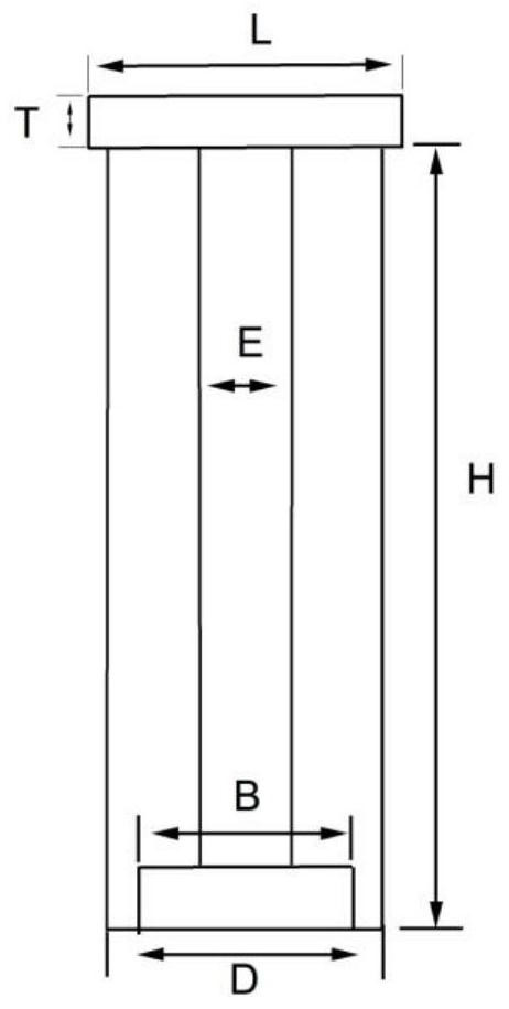
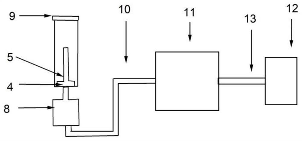
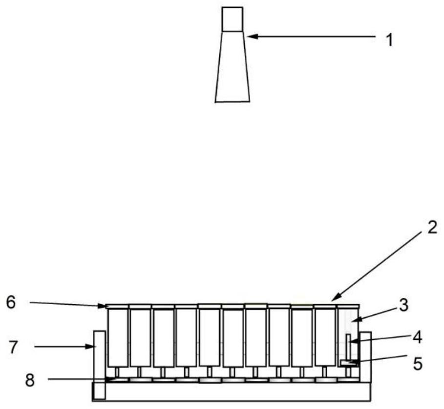
[0045] A radiation square unit structure with total reflection and no resonance structure is adopted, and the size is a structural unit of L*L=(10mm*10mm). The simulation frequency is 15GHz, then L*L=10mm*10mm satisfies the half-wavelength structure, calculated according to the following formula, the main beam can complete the pattern deflection of plus or minus 50°. The size of the glass fiber epoxy resin below is also L*L (10mm*10mm), forming a total reflection radiation unit with no resonance structure. figure 1 For the overall unit structure and connection method, figure 1 The parameters in the following table 1

[0046]

[0047]

[0048] The spacing formula is as follows:

[0049]

[0050] Where d represents the spacing of the reflective unit, λ represents the wavelength corresponding t...

Embodiment 2

[0069] First, design the elements of the reconfigurable reflectarray antenna:

[0070] It adopts a radiation square unit structure with total reflection and no resonance structure, and a half-wavelength structural unit whose size is L*L=(5mm*5mm). The size of the dielectric support structure below is L*L (5mm*5mm), forming a total reflection unit of a resonant structure.

[0071] Second, get the phase curve:

[0072] The unit is simulated in Hfss, and the reflection amplitude and phase curves are obtained by using the master-slave boundary conditions and the Floquet port simulation unit structure. Such as Figure 4 As shown, the reflection amplitude is below -1dB. Both the variation of the reflection phase with the height of the unit and the variation of the reflection phase with the frequency are linear. The reflective unit is performing well.

[0073] Third, determine the focal diameter ratio:

[0074] The focal-diameter ratio is defined as the ratio of the focal lengt...


PUM


Abstract

The invention discloses a height-adjustable reconfigurable reflective array antenna structure and a design method. The height-adjustable reconfigurable reflective array antenna structure comprises an array surface (2), and the array surface (2) is composed of more than one radiation unit (9); each radiation unit (9) is connected with a screw rod (4) of a stepping motor (8) through a supporting rod (3); the stepping motor (8) is fixed in the supporting structure (7); the design method comprises the following steps: designing the radiation unit of the reconfigurable reflective array antenna; simulating the radiation unit in Hfss, and obtaining a reflection amplitude and phase curve by using a master-slave boundary condition and a Floquet port simulation unit structure; determining the ratio of the focal length to the aperture of the reflective array antenna; acquiring the phase distribution of the antenna array through calculation in Matlab; generating a reconfigurable reflective array by using an Hfss script interface and a Matlab script tool; therefore, the technical problems that a reconfigurable reflective array antenna in the prior art is narrow in bandwidth, large in loss, complex in unit design and the like are solved.

Description

technical field [0001] The invention belongs to the technical field of antennas, in particular to a height-adjustable reconfigurable reflectarray antenna structure and a design method. Background technique [0002] The existing design method of reconfigurable reflectarray antenna is based on the design method of planar array antenna and introduces active components in the unit, such as switching diodes and varactor diodes. Reconfigurable reflectarray antennas are widely used in radar, satellite communication and other fields. However, with the continuous development and improvement of wireless communication technology, radar and communication systems are expected to have higher performance and communication efficiency. The current reconfigurable reflectarray antenna has the problems of large energy loss and narrow bandwidth due to the addition of active components. The height-adjustable reconfigurable reflectarray antenna proposed by the present invention does not require a...

Claims


Application Information

Patent Timeline
Patent Type & Authority Applications(China)
IPC IPC(8): H01Q3/04H01Q19/02H01Q19/10
CPCH01Q3/04H01Q19/02H01Q19/10
Inventor 余世星罗维雄寇娜丁召张正平
Owner GUIZHOU UNIV
Why Eureka
Try Eureka