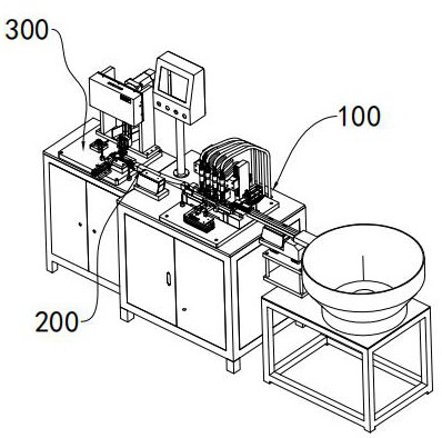
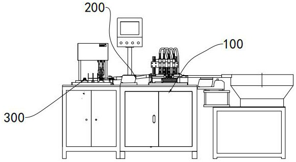
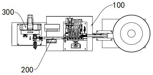
Image shell orifice burr removing mechanism and burr removing equipment

A burr removal and shell hole technology, applied in milling machine equipment, milling machine equipment details, metal processing equipment and other directions, can solve the problems of burr residue, affecting electronic components, difficult to operate equipment accurately, and achieve high production efficiency and equipment structure. The effect of simplicity and improved processing yield

Active Publication Date: 2021-09-03
IKD CO LTD
View PDF7 Cites 0 Cited by
  • Summary
  • Abstract
  • Description
  • Claims
  • Application Information

AI Technical Summary

Problems solved by technology

[0005] Many parts on the image housing need to be deburred; for example, the orifice of the housing is burred, that is, there are multiple screw ports on the image housing, and the orifice has more burrs after die-casting; due to the small internal space of the image housing , and has a certain depth, traditional equipment is difficult to operate accurately, and manual work requires more labor, and the instability of manual work is too high, resulting in burr residues that need to affect the internal electronic components

Method used


Image

  • Image shell orifice burr removing mechanism and burr removing equipment
  • Image shell orifice burr removing mechanism and burr removing equipment
  • Image shell orifice burr removing mechanism and burr removing equipment

Examples


Embodiment Construction

[0033] Preferred embodiments of the present invention will be described in detail below with reference to the accompanying drawings. Those skilled in the art will appreciate that these descriptions are only descriptive and exemplary, and should not be construed as limiting the protection scope of the present invention.

[0034] In the description of the present invention, it should be noted that the orientation or positional relationship indicated by the terms "upper", "lower", "front", "rear" etc. is based on the orientation or positional relationship shown in the drawings, and is only for convenience The present invention is described and simplified descriptions do not indicate or imply that the device or element referred to must have a specific orientation, be constructed and operate in a specific orientation, and thus should not be construed as limiting the present invention.

[0035] In the description of the present invention, it should be noted that, unless otherwise cl...


PUM


Abstract

The invention discloses an image shell orifice burr removing mechanism and burr removing equipment. The image shell orifice burr removing mechanism comprises a multi-spindle motor, a plurality of connecting rod assemblies, a milling cutter assembly and a fixing platform which are arranged from top to bottom, and a protruding positioning block used for positioning an image shell is arranged above the fixing platform; the milling cutter assembly comprises a cutter bar and a rod-shaped milling cutter, and the rod-shaped milling cutter is mounted at the front end of the cutter bar; the multi-spindle motor comprises a plurality of output shafts, the output shafts are connected with the lower ends of the connecting rod assemblies through first universal joints, the connecting rod assemblies extend upwards in an inclined mode, and the upper ends of the connecting rod assemblies are connected with the cutter bar through second universal joints; the milling cutter assembly is sleeved with a spring, so that the milling cutter assembly has a certain up-and-down stretching amount; the front end of the rod-shaped milling cutter extends to and abuts against an orifice of the image shell; and an output shaft of the multi-spindle motor drives the rod-shaped milling cutter to rotate through the connecting rod assemblies, the rotating rod-shaped milling cutter makes contact with the image shell in an elastic telescopic mode, and therefore hole opening burrs are removed.

Description

technical field [0001] The invention relates to an automatic deburring device for an image housing, in particular to a deburring mechanism for an aperture of an image housing. Background technique [0002] With the rapid development of car intelligence and driverless technology, cameras are installed in more places on cars; [0003] Usually, the camera of electronic devices is installed in the image housing, which includes a bottom shell and a cover, both of which are formed by die-casting aluminum alloy and connected by fasteners. [0004] In order to ensure the normal operation of the wires and electronic components on the camera without being damaged by burrs in the image housing, it is necessary to deburr the housing and cover. [0005] Many parts on the image housing need to be deburred; for example, the orifice of the housing is burred, that is, there are multiple screw ports on the image housing, and the orifice has more burrs after die-casting; because the internal ...

Claims


Application Information

Patent Timeline
Patent Type & Authority Applications(China)
IPC IPC(8): B23C3/12B23Q5/34B23Q3/00
CPCB23C3/12B23Q5/34B23Q3/00
Inventor 徐剑波胡宁梁忠波林梦军戴晨勇
Owner IKD CO LTD
Why Eureka
Try Eureka