Disc brake braking type cutting mechanism

A technology of cutting mechanism and braking mechanism, which is applied in the direction of manufacturing tools, metal sawing equipment, sawing machine devices, etc., can solve the problems of industrial accidents and worker injuries, and achieve the effect of convenient braking, convenient operation and compact structure

A technology of cutting mechanism and braking mechanism, which is applied in the direction of manufacturing tools, metal sawing equipment, sawing machine devices, etc., can solve the problems of industrial accidents and worker injuries, and achieve the effect of convenient braking, convenient operation and compact structure

CN113333856AActive Publication Date: 2021-09-03YANSHAN UNIV

Image

  • Disc brake braking type cutting mechanism
  • Disc brake braking type cutting mechanism
  • Disc brake braking type cutting mechanism

Examples


Embodiment Construction

[0034] In order to detail the technical content, structural features, achieved goals and effects of the present invention, the following will be described in detail in conjunction with the accompanying drawings.

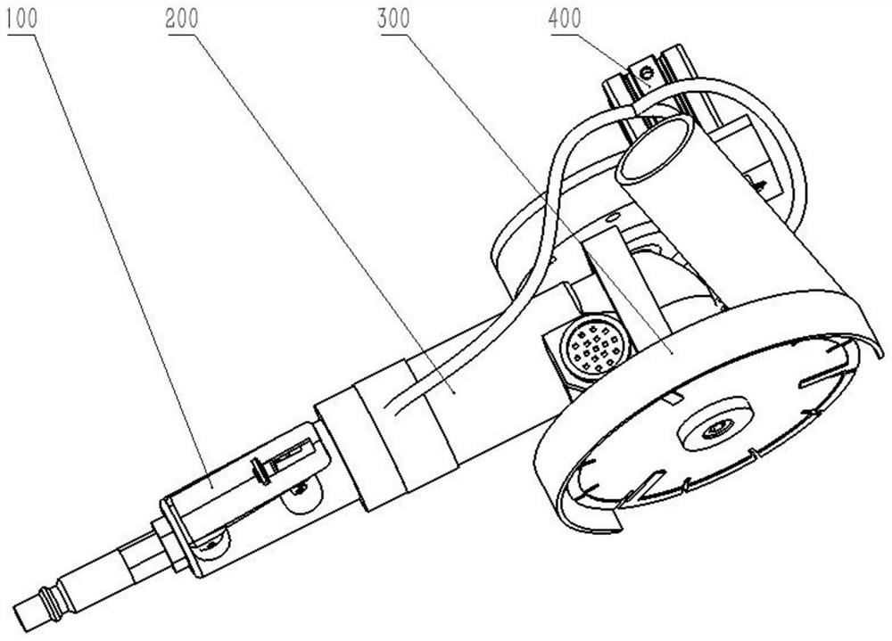
[0035] The invention provides a disc brake braking cutting mechanism, specifically a disc brake based air loss braking pneumatic cutting machine. Such asfigure 1 As shown, it includes a control mechanism 100 , a power mechanism 200 , an actuator 300 and a braking mechanism 400 .

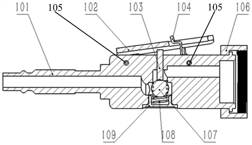
[0036] like figure 2 As shown, the control mechanism 100 is connected to the power mechanism 200 through a first threaded connection 106, and the control mechanism 100 includes a handle 101, a switch 102, a thimble 103, a buckle 104, a first threaded connection 106, a sealing ball 107, a compression spring 108 and sealing nut 109, the handle 101 is provided with a plurality of air passages, the switch 102 and the buckle 104 are connected to the outside of the handle 101 through the rotati...


PUM


Abstract

The invention relates to a disc brake braking type cutting mechanism. The brake braking type cutting mechanism comprises a control mechanism, a power mechanism, an executing mechanism and a braking mechanism, wherein the control mechanism is connected with the power mechanism through a first threaded connecting piece, and the executing mechanism and the braking mechanism are both fixedly arranged on the two sides of a shell; in the braking mechanism, a rear cover covers a front cover a rear cover and forms a brake working chamber together with the front cover, a brake pad and a friction plate are both arranged in the brake working chamber, and a first single-acting cylinder and a second single-acting cylinder are symmetrically arranged on the outer sides of the front cover and the rear cover; piston rods of the first single-acting cylinder and the second single-acting cylinder are respectively connected with the outer side surface of the brake pad, and a second air hole and the first single-acting cylinder as well as the second air hole and the second single-acting cylinder are connected through air pipes. Based on the disc brake principle, the brake pad is extruded or separated from the friction disc through the air cylinder to make contact with the friction disc, air-loss brake of a pneumatic cutting machine can be achieved, and the disc brake braking type cutting mechanism has the advantages of being compact in structure, easy to operate, reliable in effect and the like.

Description

technical field [0001] The invention relates to the technical field of pneumatic cutting machines, in particular to a disc brake cutting mechanism. Background technique [0002] Pneumatic cutting machines are very common in factories and are mostly used for cutting metal and non-metal materials. Existing pneumatic cutting machines do not have a braking mechanism, and when the ventilation is stopped, the cutting blades will still rotate for a period of time due to inertia. And because the edges of cutting discs are mostly composed of diamond sand, which is very sharp, in the case of negligence, it is very easy to cause injuries to workers, frequent industrial accidents, and there is a great potential safety hazard. In order to solve this problem, the present invention adds a braking mechanism behind the actuator of the pneumatic cutting machine, so that the cutting machine can work normally when the switch is pressed, and the brake can be braked in time when the switch is re...

Claims


Application Information

Patent Timeline
03 Sep 2021
Publication
CN113333856A
IPC
B23D45/16; B23D47/00
CPC
B23D45/16; B23D47/00
Inventors
ε΄ε‡€ε’Œ; 刘子ε₯