Steel structure special-shaped curved surface welding equipment

A special-shaped curved surface and welding equipment technology, which is applied in the field of steel structure welding, can solve the problems of poor practicability, decreased weld surface flatness, and low matching of steel structure special-shaped curved surfaces.

Active Publication Date: 2021-09-03
青岛昊宇重工有限公司
View PDF6 Cites 2 Cited by
  • Summary
  • Abstract
  • Description
  • Claims
  • Application Information

AI Technical Summary

Problems solved by technology

[0004]The object of the present invention is to provide a steel structure special-shaped curved surface welding equipment, which can realize the adjustment of the area and position of the welding table, one-button operation, simple structure, High adaptability, can speed up the cooling speed of the welding surface, prevent the slippage of the weld material caused by the influence of different surface gravity during the welding process of the special-shaped curved steel structure, optimize the flatness of the weld, improve the welding quality, and have better practicability. To solve the above-mentioned background technology, most of the existing clamping devices are strip-shaped or arc-shaped clamping surfaces, which do not match well with the special-shaped curved surface of the steel structure, and during the welding process of the special-shaped curved surface of the steel structure, the surface where the weld seam is located It is not a horizontal surface. If the weld material is not cooled in time during welding, it is easy to slide at the weld, resulting in a decrease in the flatness of the weld surface, poor welding quality, and poor practicability.

Method used


Image

  • Steel structure special-shaped curved surface welding equipment
  • Steel structure special-shaped curved surface welding equipment
  • Steel structure special-shaped curved surface welding equipment

Examples


Embodiment Construction

[0024] The technical solutions in the embodiments of the present invention will be clearly described in conjunction with the accompanying drawings in the embodiments of the present invention; it is obvious that the described embodiments are only a part of the embodiments of the present invention, not all embodiments, based on The embodiments of the present invention and all other embodiments obtained by persons of ordinary skill in the art without making creative efforts belong to the protection scope of the present invention.

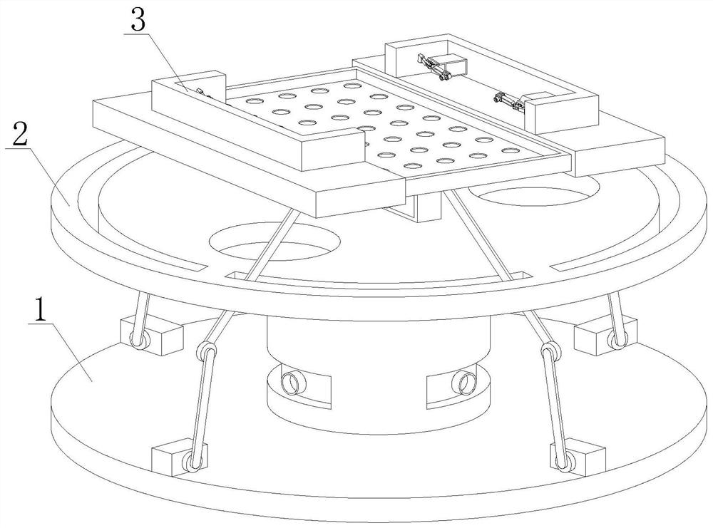
[0025] see figure 1 , a steel structure special-shaped curved surface welding equipment, including a dynamic welding base 1, a welding platform frame 2 and a welding table 3, the dynamic welding base 1 is connected to the welding platform frame 2, a welding table 3 is set above the welding platform frame 2, and the special-shaped curved surface The steel structure is placed on the welding table 3, and the dynamic welding base 1 drives the welding table...


PUM


Abstract

The invention relates to the technical field of steel structure welding, in particular to steel structure special-shaped curved surface welding equipment. The steel structure special-shaped curved surface welding equipment comprises a dynamic welding base, a welding platform frame and a welding table, the dynamic welding base is connected with the welding platform frame, and the welding table is arranged above the welding platform frame. A machine box drives a driving rotating shaft to rotate to enable a lower connecting rod to be overturned outside, a left welding rack and a right welding rack are driven to move towards the two sides and move downwards at the same time, the area and the position of the welding table are adjusted, and one-key operation is achieved. The structure is simple, adaptability is high, a switch is triggered after a middle connecting plate is pressed downwards, cold air overflows upwards from an air hole, a special-shaped curved surface steel structure in welding from bottom to top is cooled, the cooling speed of the welding face is increased, sliding of a welding seam material caused by the fact that the special-shaped curved surface steel structure is affected by gravity of different faces in the welding process is prevented, welding seam flatness is optimized, and welding quality is improved; and the position stability of the special-shaped curved surface steel structure is achieved through synchronous stretching and retracting of the output end of a telescopic rod mounting box, and practicability is higher.

Description

technical field [0001] The invention relates to the technical field of steel structure welding, in particular to welding equipment for special-shaped curved surfaces of steel structures. Background technique [0002] Steel structure is a structure composed of steel materials, which is one of the main types of building structures. The structure is mainly composed of steel beams, steel columns and steel trusses made of section steel and steel plates, and is made of silanized, pure manganese and phosphorus Chemical, washing and drying, galvanizing and other rust removal and antirust processes. The components or parts are usually connected by welds, bolts or rivets. Because of their light weight and easy construction, they are widely used in large factories, venues and superstructures. In high-rise and other fields, depending on the shape of the building, some steel structures with special-shaped surfaces will appear in the actual use process. Since ordinary connectors cannot ad...

Claims


Application Information

Patent Timeline
Patent Type & Authority Applications(China)
IPC IPC(8): B23K37/00B23K37/04
CPCB23K37/00B23K37/04B23K37/003B23K37/0426
Inventor 尹菲珍尹新中吴培利
Owner 青岛昊宇重工有限公司
Why Eureka
Try Eureka