Gear ring end face chamfering device

A technology of chamfering device and gear ring, which is applied in the direction of grinding workpiece support, grinding machine, grinding machine parts, etc., and can solve the problems of poor convenience of clamping operation

Inactive Publication Date: 2021-09-03
湖南恒裕汽车零部件有限公司
View PDF5 Cites 3 Cited by
  • Summary
  • Abstract
  • Description
  • Claims
  • Application Information

AI Technical Summary

Problems solved by technology

[0003] The purpose of the present invention is: in order to solve the problem that the traditional gear ring end face chamfering device requires the operator to manually clamp and handle, and the convenience of the clamping operation is poor, and proposes a gear ring end face chamfering device

Method used


Image

  • Gear ring end face chamfering device
  • Gear ring end face chamfering device
  • Gear ring end face chamfering device

Examples


Embodiment Construction

[0030] The following will clearly and completely describe the technical solutions in the embodiments of the present invention with reference to the accompanying drawings in the embodiments of the present invention. Obviously, the described embodiments are only some, not all, embodiments of the present invention. Based on the embodiments of the present invention, all other embodiments obtained by persons of ordinary skill in the art without creative efforts fall within the protection scope of the present invention.

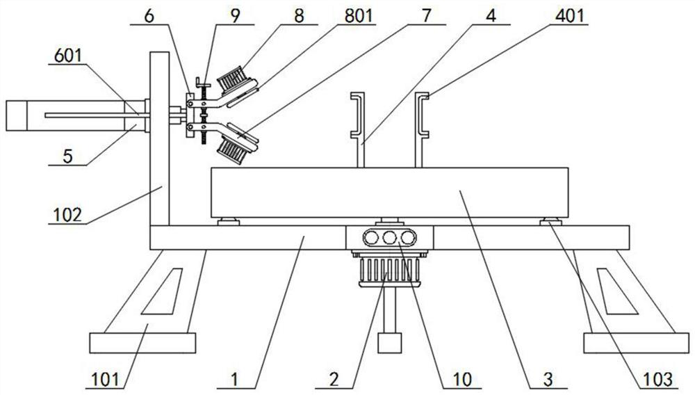
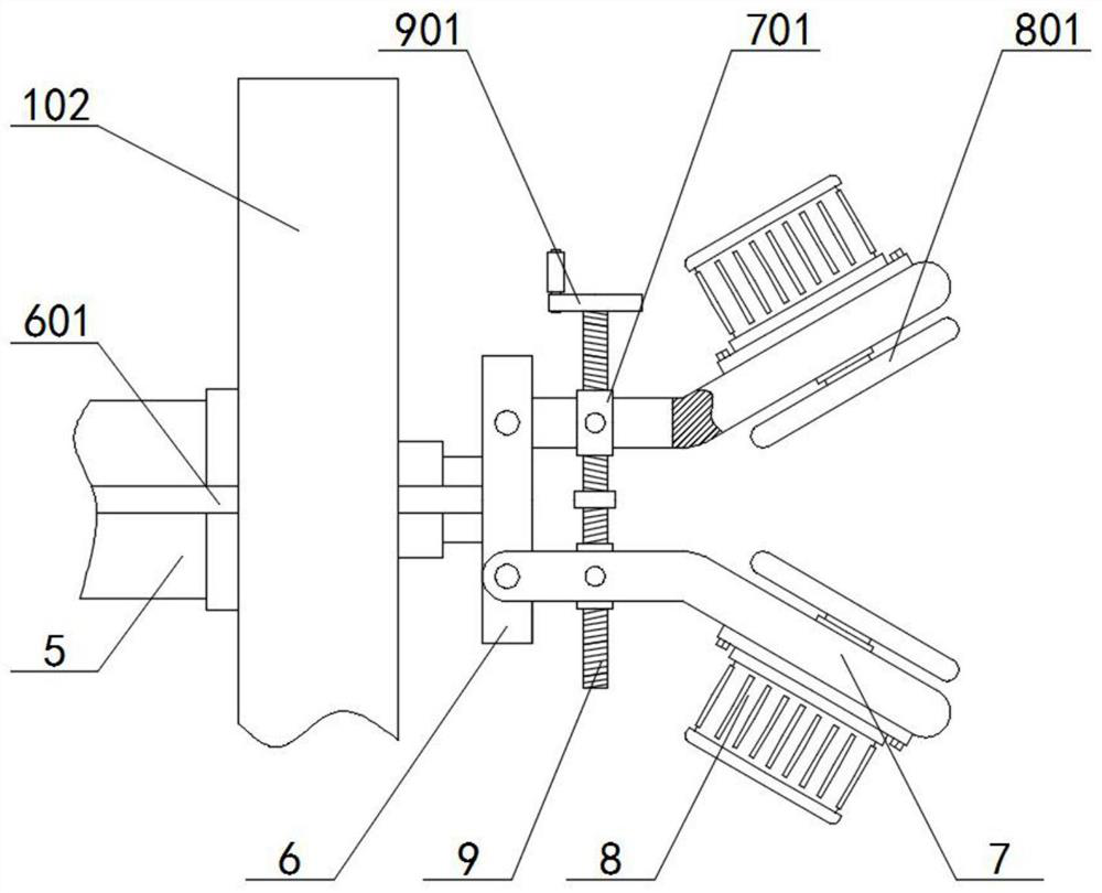
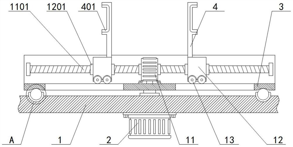
[0031] see Figure 1-4 , the present invention provides a technical solution: a gear ring end face chamfering device, including a base 1 and a grinder 8, a servo motor 2 is installed in the middle of the lower end face of the base 1, and a servo motor 2 is installed on the top of the base 1 Turntable 3, the inner middle part of turntable 3 is equipped with biaxial motor 11, the two ends of biaxial motor 11 are connected with stud 1101, and the outer symmetrical sle...


PUM


Abstract

The invention discloses a gear ring end face chamfering device. The gear ring end face chamfering device comprises a base and a grinding machine, a servo motor is installed in the middle of the lower end face of the base, a rotary table is installed at the position, located above the base, of the top of the servo motor, a double-shaft motor is installed in the middle of the inner side of the rotary table, the two ends of the double-shaft motor are in transmission connection with studs, two sets of second screw sleeves symmetrically sleeve the studs, sliding blocks are installed on the outer parts of the two sets of second screw sleeves, and inner supporting frames are fixedly connected to the top ends of the two sets of sliding blocks. According to the gear ring end face chamfering device, firstly, an inner supporting type clamping structure is adopted, automatic inner supporting and clamping treatment of a gear can be achieved, the workload of operators is reduced, the convenience of gear clamping operation is improved, and therefore chamfering machining and using of a gear disc are facilitated; and secondly, a double-face synchronous chamfering structure is adopted, synchronous chamfering treatment of the double faces of the gear can be achieved, the convenience of gear chamfering operation improved, and meanwhile, the efficiency of gear chamfering machining is improved.

Description

technical field [0001] The invention relates to the technical field of gear processing equipment, in particular to a gear ring end face chamfering device. Background technique [0002] A gear is a mechanical element with gears on the rim that continuously mesh to transmit motion and power. The application of gears in transmission has appeared very early. At the end of the 19th century, the principle of generative gear cutting method and special machine tools and cutting tools using this principle appeared one after another. With the development of production, the stability of gear operation was paid more attention. However, the existing gear ring end face chamfering devices still have deficiencies: First, most of them adopt mechanical clamping structure, which requires the direct participation of the operator when clamping the gear, and uses fasteners, fixtures and tools to fix the gear. The clamping operation is time-consuming and laborious, and the convenience of clampin...

Claims


Application Information

Patent Timeline
Patent Type & Authority Applications(China)
IPC IPC(8): B24B9/00B24B27/00B24B41/06B24B41/00
CPCB24B9/00B24B27/0076B24B27/0092B24B41/06B24B41/00
Inventor 廖庆云潘桔生江开云张雪东颜小孟
Owner 湖南恒裕汽车零部件有限公司
Why Eureka
Try Eureka