Automatic iron plate surface physical rust removal equipment for large part machining

A technology for physical derusting and large-scale parts, applied in metal processing equipment, grinding/polishing equipment, manufacturing tools, etc., can solve the problems of complex operation and low efficiency of manual derusting, reduce labor intensity, and facilitate blanking Effect

Active Publication Date: 2021-09-03
SHAANXI AOBANG FORGING
View PDF8 Cites 2 Cited by
  • Summary
  • Abstract
  • Description
  • Claims
  • Application Information

AI Technical Summary

Problems solved by technology

[0004] In order to overcome the shortcomings of low efficiency and complicated operation of manual derusting, the technical problem to be solved is to provide a kind of automatic physical derusting equipment for iron plate surface with high degree of automation, simple operation and high work efficiency.

Method used


Image

  • Automatic iron plate surface physical rust removal equipment for large part machining
  • Automatic iron plate surface physical rust removal equipment for large part machining
  • Automatic iron plate surface physical rust removal equipment for large part machining

Examples


Embodiment 1

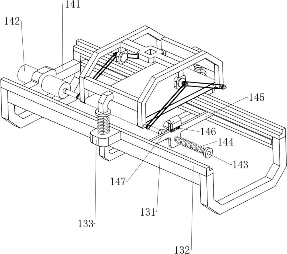
[0060] A kind of automatic physical derusting equipment for iron plate surface used for large parts processing, such as Figure 1-2 As shown, it includes a tripod 1, a carrier frame 2, a first connecting rod 3, a second connecting rod 4, a first fixed block 5, a motor 6, a rotating shaft 7, a belt 8, coarse sandpaper 9, a third connecting rod 10, L-shaped pressing bar 11, first spring 12, guiding mechanism 13 and driving mechanism 14, this equipment has 4 tripods 1, and the supporting frame 2 is arranged between the tops of the tripods 1 on the same lateral side, and the supporting frame 2 is provided with Guide mechanism 13, on the guide mechanism 13 parts, the L-shaped pressure bar 11 is slidably connected, and the first spring 12 is connected between the L-shaped pressure bar 11 and the bearing frame 2, and the third connection is provided on the L-shaped pressure bar 11 tops. Rod 10, the first connecting rod 3 is connected between the front and rear sides of the third conn...

Embodiment 2

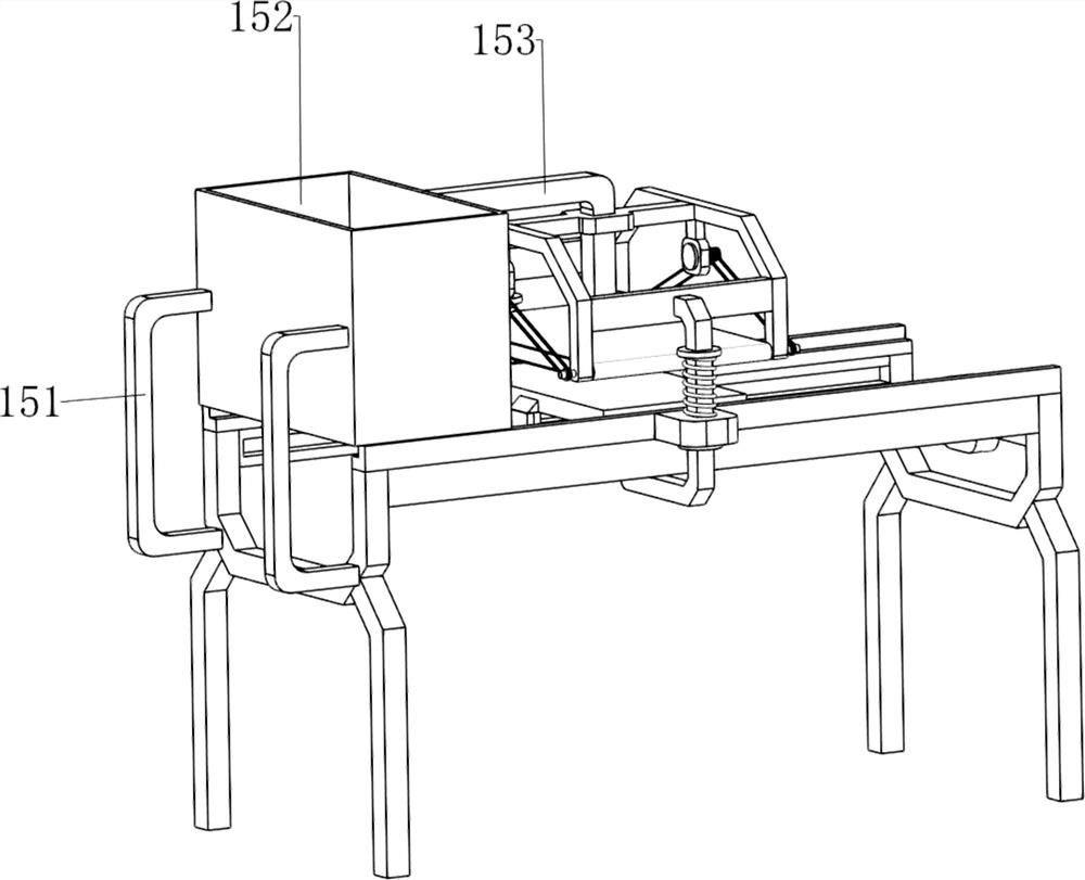
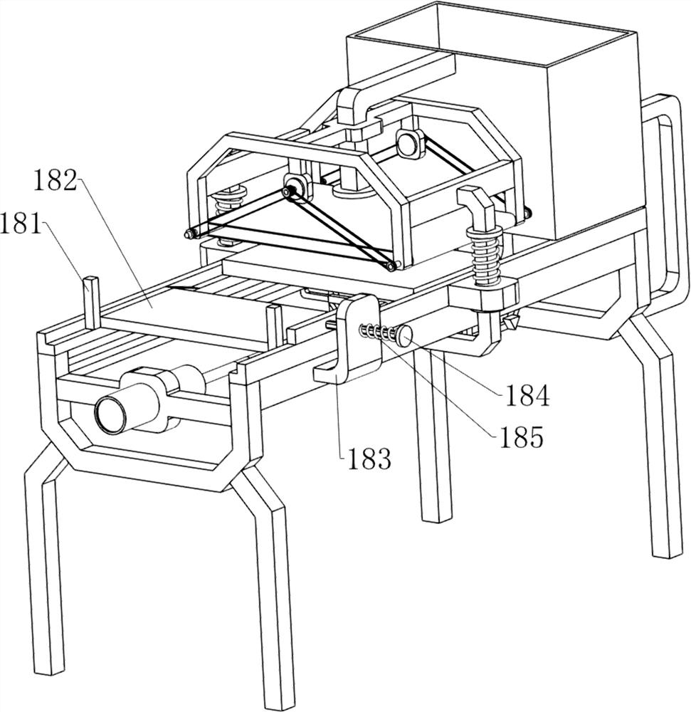
[0065] On the basis of Example 1, such as Figure 3-5 As shown, a blanking mechanism 15 is also included, and the blanking mechanism 15 includes a fourth connecting rod 151, a blanking frame 152 and a third guide rod 153, and the rear side of the carrier frame 2 on the rear side is symmetrically provided with a fourth connecting rod. 151, a blanking frame 152 is provided between the top of the fourth connecting rod 151, the bottom of the blanking frame 152 is in contact with the rear side of the top of the second guide rod 132, and the upper part of the front side of the blanking frame 152 is provided with a third guide rod 153. The guide rod 153 is slidably connected with the middle part of the second connecting rod 4 .

[0066] People put the iron plate in the blanking frame 152. When the first wedge-shaped block 147 moves forward, it drives the iron plate to move forward, so that the coarse sandpaper 9 polishes and removes the rust on the iron plate. After polishing, when t...


PUM


Abstract

The invention relates to rust removal equipment, in particular to automatic iron plate surface physical rust removal equipment for large part machining. The technical problem to be solved is to provide the automatic iron plate surface physical rust removal equipment for large part machining, which is high in automation degree, simple to operate and high in working efficiency. According to the technical scheme, the automatic iron plate surface physical rust removal equipment for large part machining comprises foot stools and bearing frames, wherein the equipment is provided with the multiple foot stools, and the bearing frames are arranged between the foot stools on the same side in the transverse direction; a guide mechanism, arranged on the bearing frames; an L-shaped pressing rod, connected to the guide mechanism component in a sliding manner; and first springs, connected between the L-shaped pressing rod and the bearing frames. Through cooperation of the pressing mechanism and the driving mechanism, the equipment can automatically grind and derust an iron plate, and the labor intensity of people is reduced.

Description

technical field [0001] The invention relates to a derusting device, in particular to an automatic physical derusting device for the surface of an iron plate used for processing large parts. Background technique [0002] Nowadays, with the continuous development of society and the continuous acceleration of social construction, iron plates are one of the indispensable materials during construction. In order to advocate energy conservation, unused iron plates will be recycled and reused. Recycled iron plates Some of them are covered with rust due to long-term placement and cannot be used directly. Therefore, rust treatment is required. The existing iron plate derusting mainly depends on manual work, which has problems of incomplete derusting, low work efficiency and complicated operation. shortcoming. [0003] Therefore, it is necessary to develop a high degree of automation, simple operation and high work efficiency for the automatic physical derusting equipment on the surfa...

Claims


Application Information

Patent Timeline
IPC IPC(8): B24B27/033B24B41/02B24B41/00
CPCB24B27/033B24B27/0092B24B41/02B24B41/00Y02P70/10
Inventor 罗丽珍
Owner SHAANXI AOBANG FORGING
Why Eureka
Try Eureka