
Additional shaft guide rail structure of universal industrial robot

A technology of industrial robots and additional axes, applied in manipulators, manufacturing tools, etc., can solve problems such as affecting the precision of guide rails and robots, affecting working precision and stability, and loosening the connection between the base and the guide rails, and achieve good system stability. , protect precision and stability, reduce the effect of back and forth shaking

Inactive Publication Date: 2021-09-03
JIANGSU UNIV OF SCI & TECH
View PDF6 Cites 2 Cited by
  • Summary
  • Abstract
  • Description
  • Claims
  • Application Information

AI Technical Summary

Problems solved by technology

[0003] However, these current guide rail structures have certain limitations. The traditional guide rail structure is complex, and subsequent maintenance is time-consuming and labor-intensive. Maintenance requires the disassembly of most structures, which is not only inefficient, but also easily affects the precision of the guide rail and the robot’s working movement. Moreover, the splashed oil and parts debris are easy to adhere to the motor and internal drive mechanism during work, which is easy to increase the failure rate. The movement of most robots on the guide rail is prone to mechanical fatigue, and long-term work is likely to cause damage to the joint between the base and the guide rail. Looseness affects the precision and stability of the work

Method used


Image

  • Additional shaft guide rail structure of universal industrial robot
  • Additional shaft guide rail structure of universal industrial robot
  • Additional shaft guide rail structure of universal industrial robot

Examples


Embodiment Construction

[0036] The following will clearly and completely describe the technical solutions in the embodiments of the present invention with reference to the accompanying drawings in the embodiments of the present invention. Obviously, the described embodiments are only some, not all, embodiments of the present invention.

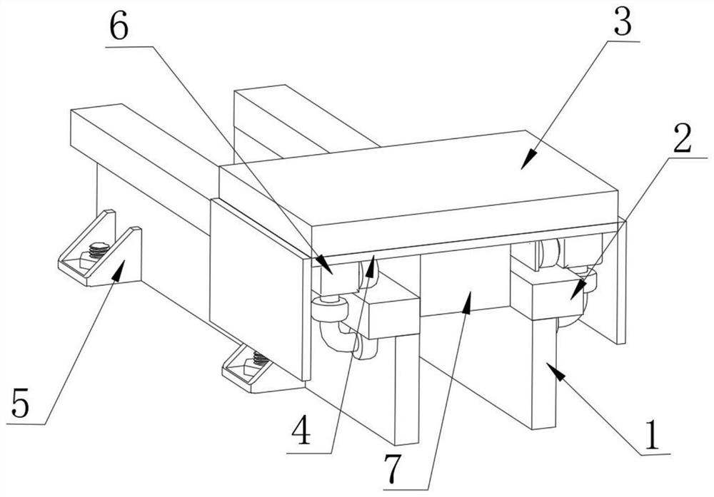
[0037] refer to Figure 1-10 , a general-purpose industrial robot additional shaft guide rail structure, including:

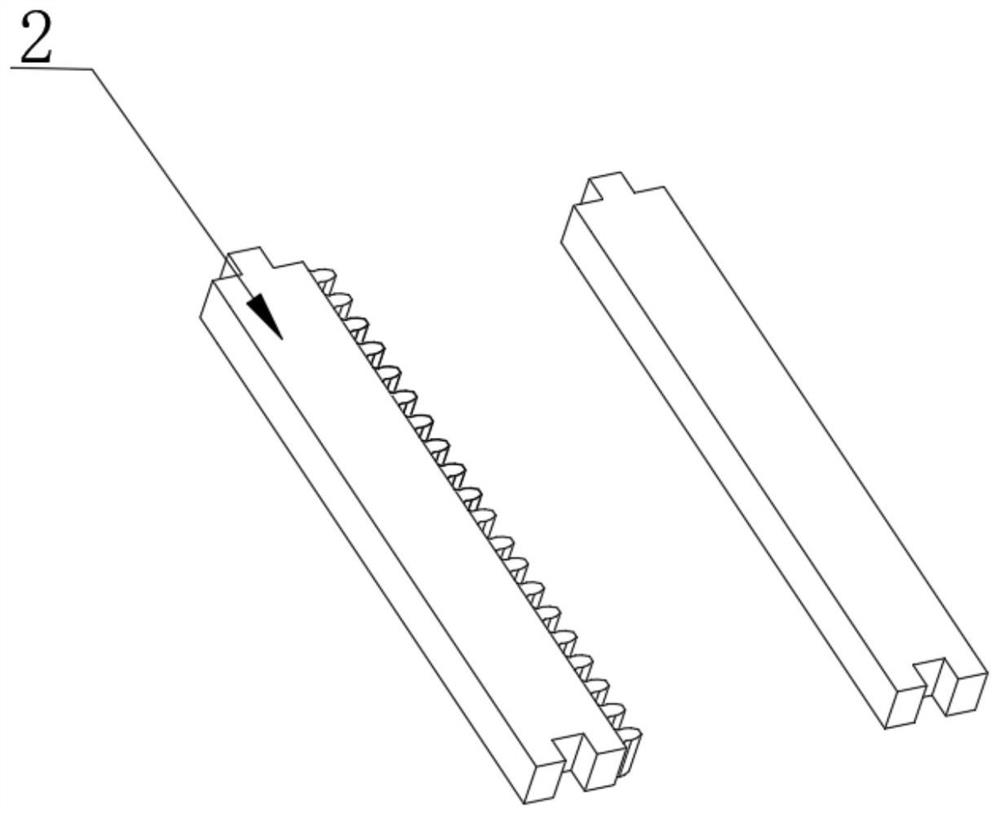
[0038] Fixed steel block 1, the side of fixed steel block 1 is welded with fixed base 5, the top of fixed steel block 1 is welded with guide rail 2, and the top of 2 is placed with slide block 6, and the top of slide block 6 is fixedly installed with driving board 4, drives The top of the plate 4 is fixedly installed with a robot installation base 3;

[0039] A drive system, used to drive the drive plate 4;

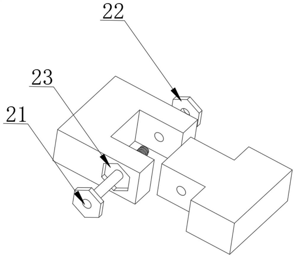
[0040] The tightening system is used for the slider 6 to perform tightening operation along the guide rail 2;

[0041] like image 3 , the sid...


PUM


Abstract

The invention discloses an additional shaft guide rail structure of a universal industrial robot. The structure comprises a fixed steel block, a fixed base is welded to the side surface of the fixed steel block, a guide rail is welded to the top of the fixed steel block, a sliding block is placed at the top of the guide rail, a driving plate is fixedly mounted at the top of the sliding block, a robot mounting base is fixedly mounted at the top of the driving plate, a driving system is used for driving the driving plate, and a tightening system is used for tightening the sliding block along the guide rail. According to the structure, each important part is provided with a protection mechanism, a buffer device is arranged between the guide rail, and the bearing tightening device is arranged so that external interference is prevented, the precision of the system can be improved, the service lifetime of the system is prolonged, the operation cost is reduced, the length of the guide rail can be randomly increased and reduced in the later stage due to the structural characteristics of the guide rail, the operation is simple, and the practicability is high.

Description

technical field [0001] The invention relates to the technical field of industrial robots, in particular to a general-purpose industrial robot auxiliary shaft guide rail structure. Background technique [0002] Industrial robots are multi-joint manipulators or multi-degree-of-freedom machine devices that are widely used in the industrial field. It is fixed on the base, and the mobile function is completed by moving the base on the guide rail, so as to complete multi-angle or multi-path work. [0003] However, these current guide rail structures have certain limitations. The traditional guide rail structure is complex, and subsequent maintenance is time-consuming and labor-intensive. Maintenance requires the disassembly of most structures, which is not only inefficient, but also easily affects the precision of the guide rail and the robot’s working movement. Moreover, the splashed oil and parts debris are easy to adhere to the motor and internal drive mechanism during work, w...

Claims


Application Information

Patent Timeline
Patent Type & Authority Applications(China)
IPC IPC(8): B25J5/02B25J19/00
CPCB25J5/02B25J19/00
Inventor 李立红
Owner JIANGSU UNIV OF SCI & TECH
Learn More