
Steep slope slow descent control method, system, vehicle and storage medium

A control method and braking system technology, applied in the field of systems, vehicles and storage media, and steep slope descent control methods, can solve problems such as endangering driving safety, failure, low vehicle speed accuracy and stability, and prevent overuse, Improve accuracy and ensure driving safety

Active Publication Date: 2021-09-03
CHINA FIRST AUTOMOBILE
View PDF22 Cites 1 Cited by
  • Summary
  • Abstract
  • Description
  • Claims
  • Application Information

AI Technical Summary

Problems solved by technology

[0003]The vehicle speed control link of the existing steep slope descent control system is relatively simple, most of which only have a simple closed-loop control process of vehicle speed, without considering the influence of vehicle state parameters on vehicle speed control, such as State parameters such as vehicle mass, slope, brake disc friction coefficient, etc., the accuracy and stability of vehicle speed are low; moreover, the existing system is relatively simple in the distribution process of braking torque required for vehicle speed control, and less consideration is given to vehicle actuators The impact of characteristics on the distribution process of demanded braking torque, such as the temperature of the brake disc, the energy recovery feedback torque of the drive motor of the electric vehicle, or the anti-drag torque of the engine of the fuel vehicle, etc., when driving downhill for a long time, it is easy to cause the braking system to bear There is a risk of failure due to excessive load, which endangers driving safety

Method used


Image

  • Steep slope slow descent control method, system, vehicle and storage medium
  • Steep slope slow descent control method, system, vehicle and storage medium
  • Steep slope slow descent control method, system, vehicle and storage medium

Examples


Embodiment 1

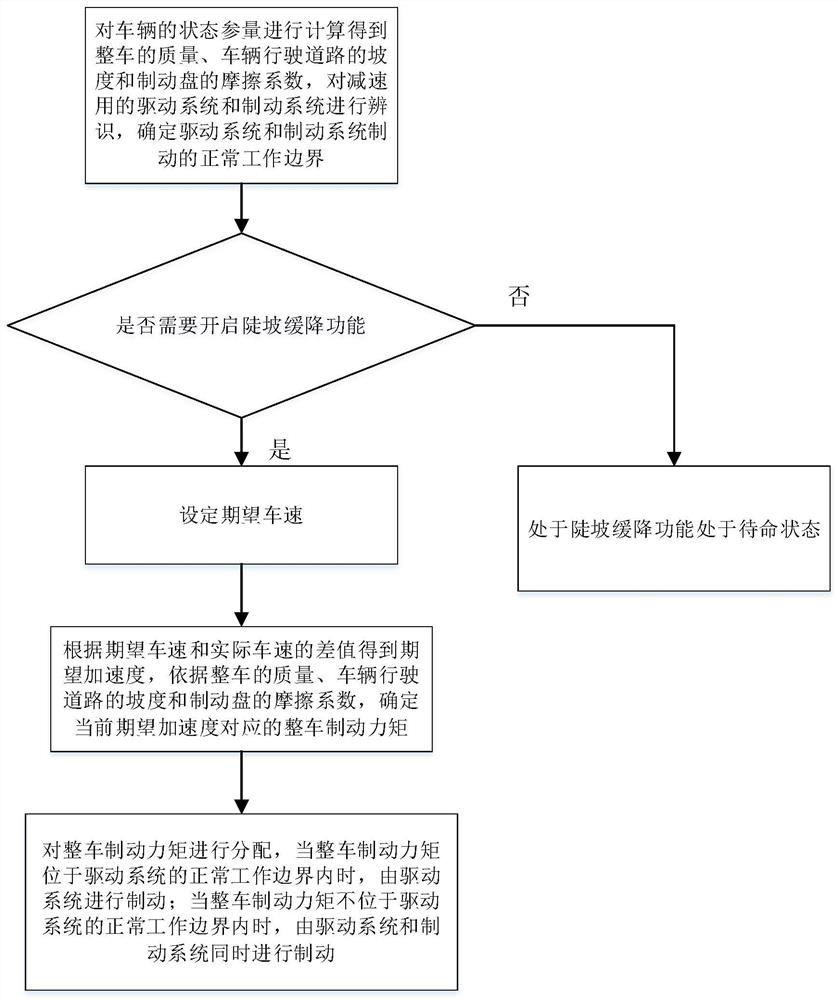
[0045] As people's requirements for driving experience are getting higher and higher, cars are constantly developing in the direction of intelligence. In the process of driving, it is inevitable to face downhill working conditions. In such working conditions, the driver needs to control the vehicle in real time and accurately to ensure the safety of driving. In order to reduce the driver's work intensity, effectively and accurately control the vehicle speed, and reasonably distribute the braking torque to ensure driving safety, such as figure 1 As shown, the present invention provides a steep slope descent control method. The steep slope descent control method comprises the following steps:

[0046] S1. Calculate the state parameters of the vehicle to obtain the mass of the vehicle, the slope of the road the vehicle is driving on and the friction coefficient of the brake disc, identify the driving system and braking system for deceleration, and determine the braking of the dr...

Embodiment 2

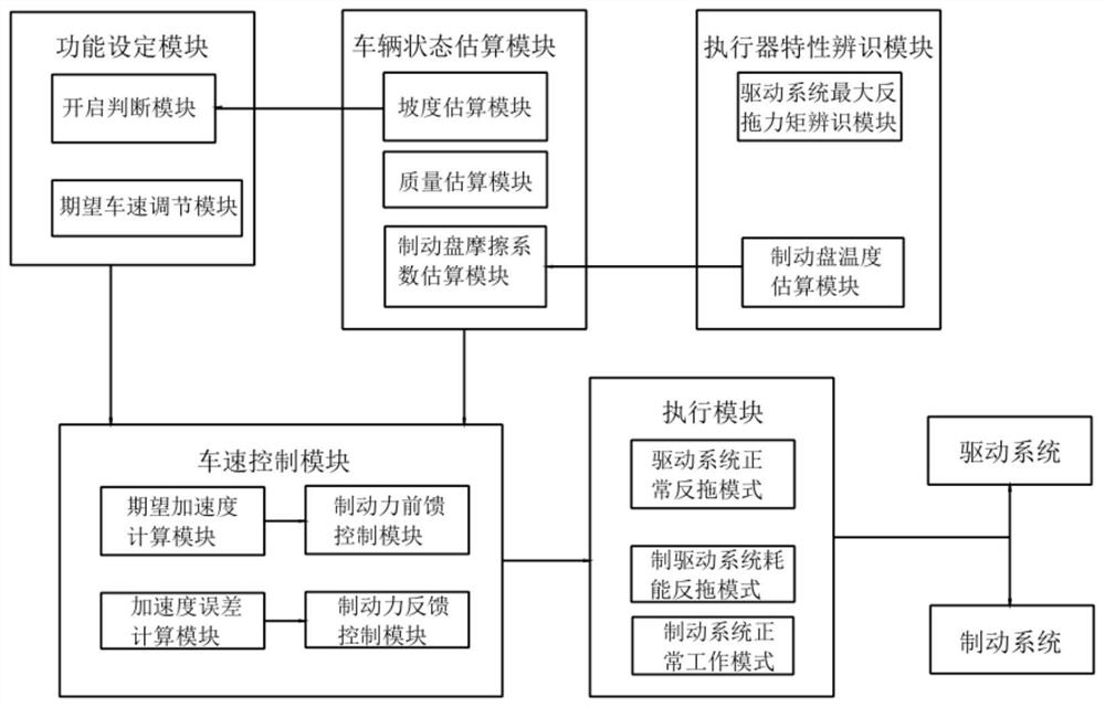
[0067] like figure 2 As shown, in order to be able to reasonably distribute the braking torque when the vehicle is descending steeply, so as to ensure driving safety. This embodiment provides a steep slope descent control system. The steep slope descent control system mainly includes: an actuator characteristic identification module, a vehicle state estimation module, a function setting module, a vehicle speed control module, and an execution module.

[0068] Among them, the actuator characteristic identification module is used to determine the normal working boundary of the drive system and the braking system; the vehicle state estimation module is used to estimate the mass of the vehicle, the slope of the road the vehicle is driving on and the friction coefficient of the brake disc; the function design The determination module is used to judge whether to enable the steep slope descent function and set the expected vehicle speed; the vehicle speed control module is connected...

Embodiment 3

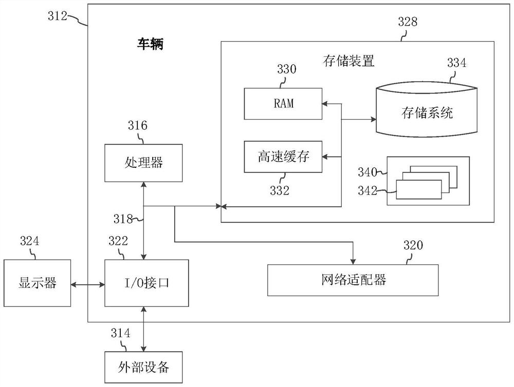
[0076] image 3 It is a schematic structural diagram of the vehicle in this embodiment. image 3 A block diagram of an exemplary vehicle 312 for implementing embodiments of the invention is shown. image 3 The vehicle 312 shown is only an example, and should not impose any limitation on the functions and scope of use of the embodiments of the present invention.

[0077] like image 3 As shown, vehicle 312 takes the form of a universal terminal. Components of the vehicle 312 may include, but are not limited to: a vehicle body (not shown), one or more processors 316, a storage device 328, and a bus 318 connecting various system components (including the storage device 328 and the processor 316).

[0078] Bus 318 represents one or more of several types of bus structures, including a storage device bus or controller, a peripheral bus, an accelerated graphics port, a processor, or a local bus using any of a variety of bus structures. For example, these architectures include but a...


PUM


Abstract

The invention relates to the technical field of automobiles, in particular to a steep slope slow descent control method, a system, a vehicle and a storage medium. The steep slope slow descent control method comprises the following steps: S1, calculating state parameters of the vehicle to obtain the mass of the whole vehicle, the gradient of a vehicle driving road and the friction coefficient of a brake disc; recognizing a driving system and a braking system for speed reduction, and determining normal working boundaries of braking of the driving system and the braking system; s2, whether the steep slope slow descent function needs to be started or not is judged, and if yes, the next step is executed; s3, setting an expected vehicle speed; s4, obtaining expected acceleration according to the difference value between the expected vehicle speed and the actual vehicle speed, and determining the whole vehicle braking torque corresponding to the current expected acceleration; and S5, distributing the braking torque of the whole vehicle. According to the invention, the braking torque can be reasonably distributed, and the driving safety is ensured.

Description

technical field [0001] The invention relates to the technical field of automobiles, in particular to a steep slope descent control method, system, vehicle and storage medium. Background technique [0002] As people's requirements for driving experience are getting higher and higher, cars are constantly developing in the direction of intelligence. In the process of driving, it is inevitable to face downhill working conditions. In such working conditions, it is necessary to effectively control the car to ensure the safety of driving. [0003] The vehicle speed control link of the existing steep slope descent control system is relatively simple. Most of them only have a simple closed-loop control process of vehicle speed, and do not consider the influence of vehicle state parameters on vehicle speed control, such as state parameters such as vehicle mass, slope, and brake disc friction factor. The accuracy and stability of the vehicle speed are relatively low; moreover, the exi...

Claims


Application Information

Patent Timeline
IPC IPC(8): B60W30/18B60W40/105B60W40/10B60W40/076B60W40/00
CPCB60W30/18009B60W30/18109B60W40/105B60W40/10B60W40/076B60W40/00Y02T10/72
Inventor 张建厉健峰王相玲姜洪伟李林润王御张苏铁王珊
Owner CHINA FIRST AUTOMOBILE
Learn More